
Millimeter-wave non-line of sight analysis

a non-line of sight, millimeter wave technology, applied in diversity/multi-antenna systems, transmitter monitoring, transmission monitoring, etc., can solve problems such as high path loss, and achieve the effect of reducing path loss and high path loss

Active Publication Date: 2021-04-29
SONY CORP
View PDF0 Cites 4 Cited by
  • Summary
  • Abstract
  • Description
  • Claims
  • Application Information

AI Technical Summary

Benefits of technology

This patent is about a technology that can be applied to mmWave frequencies, such as 60 GHz, to estimate non-line of sight (NLOS) propagation in enclosed spaces like indoor living rooms. The technology can also find practical alternatives to the LOS path in case of blockage. The patent text includes a detailed description of the technology without placing limitations on it. The technical effects of the technology are improved estimation of NLOS propagation and practical alternatives to the LOS path in mmWave, Wi-Fi, and wireless networking scenarios.

Problems solved by technology

Yet, mmWave systems generally utilize directional antennas for overcoming unfavorable propagation scenarios which result from high path loss at mmWave frequencies.

Method used


Image

  • Millimeter-wave non-line of sight analysis
  • Millimeter-wave non-line of sight analysis
  • Millimeter-wave non-line of sight analysis

Examples


Embodiment Construction

1. Introduction and Scenario

[0023]The present disclosure utilizes an indoor room (e.g., living room) as its example for performing channel measurements in devising a method for understanding and estimating channel parameters, such as angle-of-departure (AoD), angle-of-arrival (AoA), line-of-sight, and non line-of-sight paths.

[0024]A method is described for deriving omni-directional power delay profiles (omni-PDPs) from directional PDP measurements, and for inferring AoD, AoA and ray path information from measured channel data. The method has also been validated based on comparing signal measurements versus ray tracing simulations.

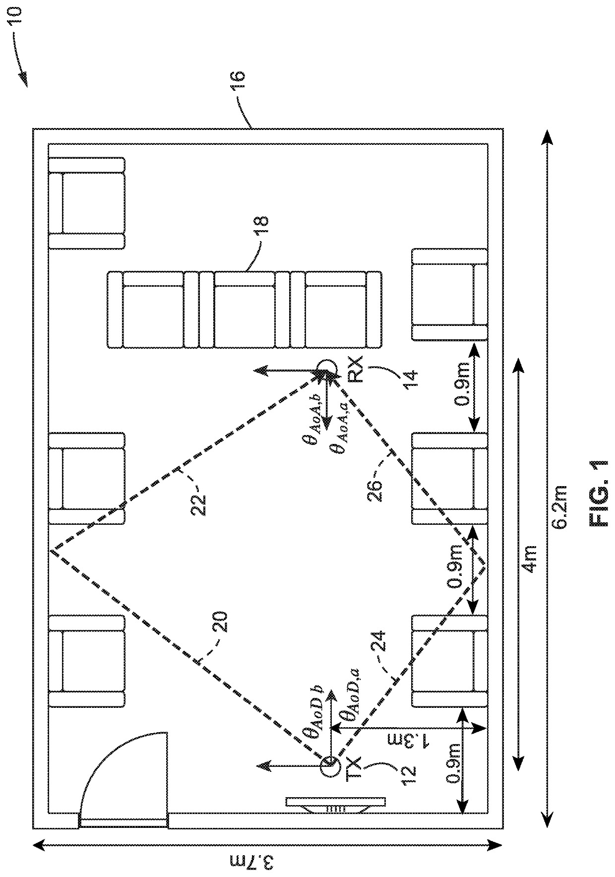
[0025]FIG. 1 illustrates an example venue 10 within which channel sounding measurements were performed using mmWave communication stations having phased array antennas. By way of example and not limitation, the specific hardware utilizes 60 GHz phased arrays, although the present disclosure is generally applicable to the mmW range from 30 to 300 GHz. The ex...


PUM


Abstract

Reducing the effects of path loss in millimeter wave (mmWave) directional communications by performing channel measurements estimating non-line of sight (NLOS) blockages, to determine angle-of-departure (AoD) and angle-of-arrival (AoA) and gain of identified paths so that directional antennas can be reconfigured to overcome unfavorable propagation conditions and reduce path losses.

Description

CROSS-REFERENCE TO RELATED APPLICATIONS[0001]This application is a continuation of U.S. patent application Ser. No. 62 / 925,621 filed on Oct. 24, 2019, incorporated herein by reference in its entirety.STATEMENT REGARDING FEDERALLY SPONSORED RESEARCH OR DEVELOPMENT[0002]Not ApplicableNOTICE OF MATERIAL SUBJECT TO COPYRIGHT PROTECTION[0003]A portion of the material in this patent document may be subject to copyright protection under the copyright laws of the United States and of other countries. The owner of the copyright rights has no objection to the facsimile reproduction by anyone of the patent document or the patent disclosure, as it appears in the United States Patent and Trademark Office publicly available file or records, but otherwise reserves all copyright rights whatsoever. The copyright owner does not hereby waive any of its rights to have this patent document maintained in secrecy, including without limitation its rights pursuant to 37 C.F.R. § 1.14.BACKGROUND1. Technical ...

Claims


Application Information

Patent Timeline
IPC IPC(8): H04B7/08H04B17/318H04B17/364H04B17/10
CPCH04B7/086H04B17/318H04B7/0828H04B17/102H04B17/364H04B17/309H01Q1/22H04B7/0617
Inventor XIN, LIANGXIAOBALAKRISHNAN, SARANKUMAR
Owner SONY CORP
Learn More