Timepiece movement and timepiece
- Summary
- Abstract
- Description
- Claims
- Application Information
AI Technical Summary
Benefits of technology
Problems solved by technology
Method used
Image

Examples
first embodiment
[0035]In general, a mechanical body including a driving part of a timepiece is referred to as a “movement”. A state where a dial and hands are attached to the movement and the movement is put into a timepiece case to prepare a finished product is referred to as a “complete state” of the timepiece. Out of both sides of a main plate configuring a substrate of the timepiece, a side on which a glass of the timepiece case is present (that is, a side on which the dial is present) is referred to as a “back side” of the movement. In addition, out of both sides of the main plate, a side on which a case back cover of the timepiece case is present (that is, a side opposite to the dial) is referred to as a “front side” of the movement.
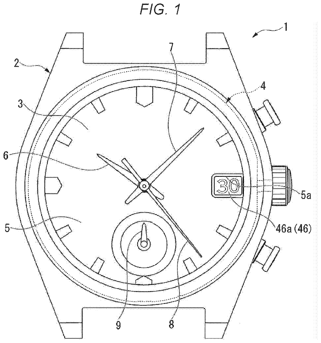
[0036]FIG. 1 is an external view of a timepiece which illustrates a first embodiment.
[0037]As illustrated in FIG. 1, in the complete state of a timepiece 1 according to the present embodiment, a timepiece case 2 having a case back cover (not illustrated) and a gla...
second embodiment
[0078]FIG. 7 is a plan view illustrating a part of a movement according to a second embodiment, and is a view when a first train wheel group is viewed from the front side.
[0079]In the first embodiment illustrated in FIG. 5, both the first reference load unit 60A and the second reference load unit 60B are provided in wheel gears of at least one of the hour train wheel 31 and the calendar train wheel 41. In contrast, the second embodiment illustrated in FIG. 7 is different from the first embodiment in that the second reference load unit 60B is provided in a wheel gear different from that of the hour train wheel 31 and the calendar train wheel 41. Configurations other than those described below are the same as those according to the first embodiment.
[0080]As illustrated in FIG. 7, a first train wheel group 30A according to the present embodiment has a configuration as follows. A dedicated wheel gear 36 is added to the first train wheel group 30 according to the first embodiment, and th...
third embodiment
[0084]FIG. 8 is a plan view illustrating a part of a movement according to a third embodiment, and is a view when a first train wheel group is viewed from the front side.
[0085]The third embodiment illustrated in FIG. 8 is different from the first embodiment in that the second intermediate hour wheel 33 rotates at the reduction ratio of 36 with respect to the rotor 22 of the first motor 20A. Configurations other than those described below are the same as those according to the first embodiment.
[0086]As illustrated in FIG. 8, a first train wheel group 30B according to the present embodiment changes the reduction ratio of the second intermediate hour wheel 33 with respect to the rotor 22 of the first motor 20A, compared to the first train wheel group 30 according to the first embodiment. The number of teeth of the second intermediate hour wheel gear 33a of the second intermediate hour wheel 33 is 72. The second intermediate hour wheel 33 rotates at the reduction ratio of 6 with respect...
PUM
 Abstract
Description
Claims
Application Information
 - R&D
- Intellectual Property
- Life Sciences
- Materials
- Tech Scout
- Unparalleled Data Quality
- Higher Quality Content
- 60% Fewer Hallucinations
Browse by: Latest US Patents, China's latest patents, Technical Efficacy Thesaurus, Application Domain, Technology Topic, Popular Technical Reports.
© 2025 PatSnap. All rights reserved.Legal|Privacy policy|Modern Slavery Act Transparency Statement|Sitemap|About US| Contact US: help@patsnap.com