Contour mode prediction

a prediction mode and contour mode technology, applied in the field of contour mode prediction, can solve the problems of reducing coding efficiency, high signaling cost, and reducing signaling efficiency, so as to reduce prediction error, increase coding efficiency, and reduce the effect of side information

Active Publication Date: 2021-04-15
FRAUNHOFER GESELLSCHAFT ZUR FOERDERUNG DER ANGEWANDTEN FORSCHUNG EV
View PDF17 Cites 1 Cited by
  • Summary
  • Abstract
  • Description
  • Claims
  • Application Information

AI Technical Summary

Benefits of technology

[0019]It is basic idea underlying the subject-matter of the present application that a coding efficiency increase is achievable by applying a prediction mode to predict a number of blocks of a picture by extrapolating a neighborhood of the respective block into the block along a direction which varies across the respective block. That is, according to the prediction mode of the present application, i.e., a contour prediction mode, the prediction direction for the current block to be predicted is changed based on the sample block which has been previously predicted. That means, it is possible to change the prediction direction within the same block between the lines of the samples of the block is composed of, and therefore, a larger block is predicted more preciously with less prediction error. The side information, in turn, may be kept low and, additionally, large block size (a coarse block granularly), is feasible, so that it is possible to reduce signaling costs even further and as a result improve the coding efficiency.
[0020]In accordance with the embodiments of the present application, the direction across the respective block in unit of lines of samples the respective block is composed of, or in unit of groups of lines of samples into which the block is partitioned, is varied based on one or more offset values indicating an offset of sample positions at which the neighborhood is to be sampled for predicting a predetermined line or predetermined group of lines relative to further sample positions at which the neighborhood is to be sampled for predicting a further line or further group of lines adjacent to the predetermined line or predetermined group of lines. That is, the prediction direction is changed for each line of samples (e.g., the line of blocks to be predicted) or each of groups of lines of samples (the group of lines of samples to be predicted), based on the determined offset value. Therefore, it is possible to improve the predict efficiency for a larger block.

Problems solved by technology

Regarding intra-picture prediction and especially the angular prediction mode described above, this might be inefficient.
However, this solution tends to result in higher signaling costs and smaller instead of larger blocks, and therefore, as a result it causes decreasing the coding efficiency.

Method used


Image

  • Contour mode prediction
  • Contour mode prediction
  • Contour mode prediction

Examples


Embodiment Construction

[0035]The following description of the figures starts with a presentation of a description of video encoder and video decoder of a block-based predictive codec for coding pictures of a video in order to form an example for a coding framework into which embodiments for a composed prediction codec may be built in. The video encoder and video decoder are described with respect to FIGS. 6 to 8. Thereinafter the description of embodiments of the concept of the prediction mode of the present application are presented along with a description as to how such concepts could be built into the video encoder and decoder of FIGS. 6 and 7, respectively, although the embodiments described with the subsequent FIG. 9 and following, may also be used to form video encoder and video decoders not operating according to the coding framework underlying the video encoder and video decoder of FIGS. 6 and 7.

[0036]FIG. 6 shows an apparatus for predictively coding a video 11 composed of a sequence of pictures ...


PUM


Abstract

A video decoder and method for supporting a prediction mode for predicting blocks of a video is configured to predict each of the blocks by extrapolating a neighborhood of the respective block into the block along a direction which varies across the respective block.

Description

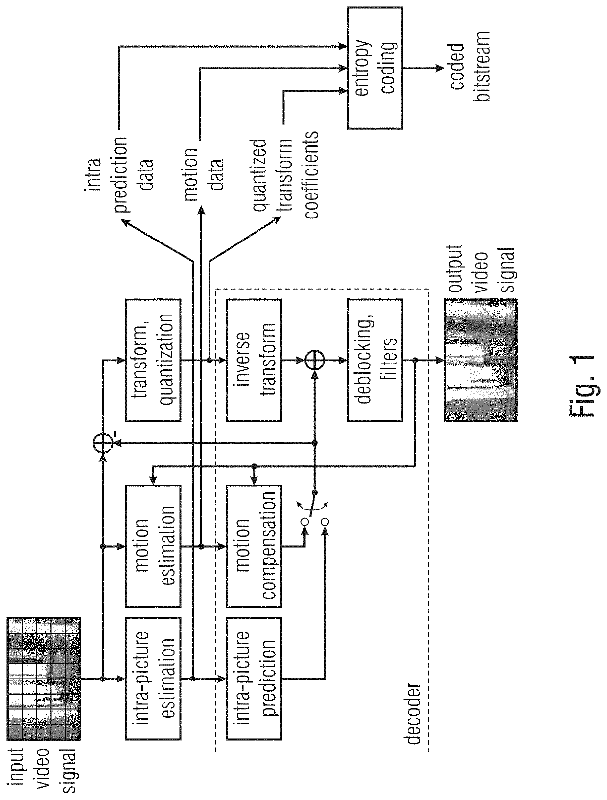
CROSS-REFERENCES TO RELATED APPLICATIONS[0001]This application is a continuation of copending International Application No. PCT / EP2019 / 066908, filed Jun. 25, 2019, which is incorporated herein by reference in its entirety, and additionally claims priority from European Application No. EP 18180230.7, filed Jun. 27, 2018, which is incorporated herein by reference in its entirety.[0002]The present application is concerned with video coding / decoding.BACKGROUND OF THE INVENTION[0003]All relevant video coding standards, like AVC / H.264 or HEVC / H.265, follow the so-called hybrid approach as shown, for example, in FIG. 1, where predictive coding is combined with transform coding of the prediction residual. For generating the prediction signal, two possible modes are supported by these standards, namely INTRA prediction and INTER prediction. In AVC / H.264, the decision between these two modes can be made at macroblock (16×16 luma samples) level, and in HEVC / H.265 at Coding Unit (CU) level, whi...

Claims


Application Information

Patent Timeline
Patent Type & Authority Applications(United States)
IPC IPC(8): H04N19/59H04N19/132H04N19/119H04N19/176
CPCH04N19/59H04N19/176H04N19/119H04N19/132H04N19/105H04N19/11H04N19/593H04N19/70
Inventor MERKLE, PHILIPPSCHWARZ, HEIKOMARPE, DETLEVWIEGAND, THOMAS
Owner FRAUNHOFER GESELLSCHAFT ZUR FOERDERUNG DER ANGEWANDTEN FORSCHUNG EV
Why Eureka
Try Eureka