
System for Rotating Detonation Combustion

Pending Publication Date: 2021-04-15
GENERAL ELECTRIC CO
View PDF2 Cites 5 Cited by
  • Summary
  • Abstract
  • Description
  • Claims
  • Application Information

AI Technical Summary

Benefits of technology

The technical effects of this patent are not clearly stated, but it is described as a new invention that solves a problem or improves an existing technology. The text may describe aspects and advantages of the invention, or it may be clear from the description that the technical effects are not specified. More information on the invention's technical effects can be found by practicing the invention and understanding the details provided in the patent text.

Problems solved by technology

However, continuous detonation systems are challenged to sustain detonation in general, or to sustain detonation across various operating conditions.
Without sustaining detonation of the fuel / air mixture, detonation combustion systems may be insufficiently operable for use in heat engines.

Method used


Image

  • System for Rotating Detonation Combustion
  • System for Rotating Detonation Combustion
  • System for Rotating Detonation Combustion

Examples


Embodiment Construction

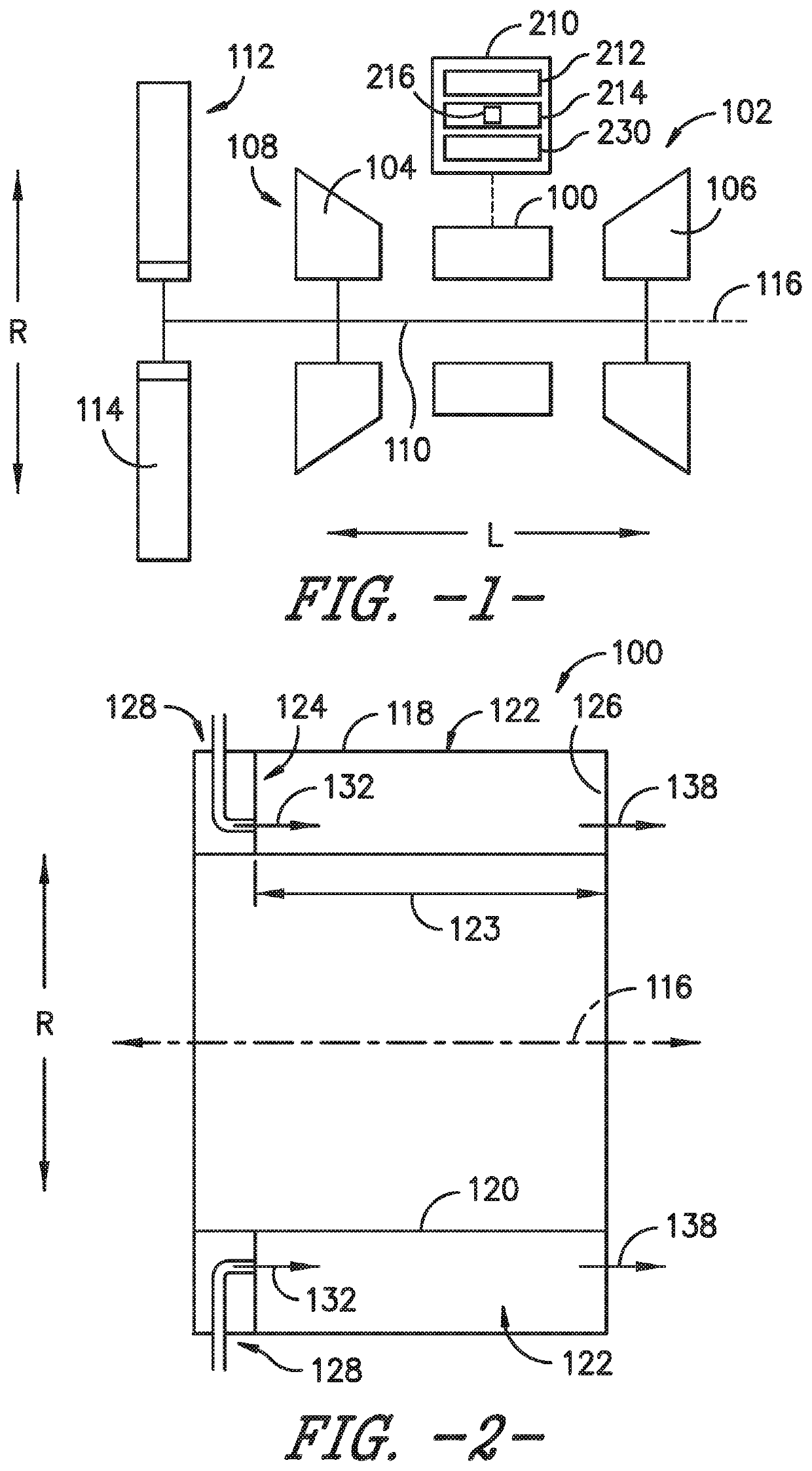
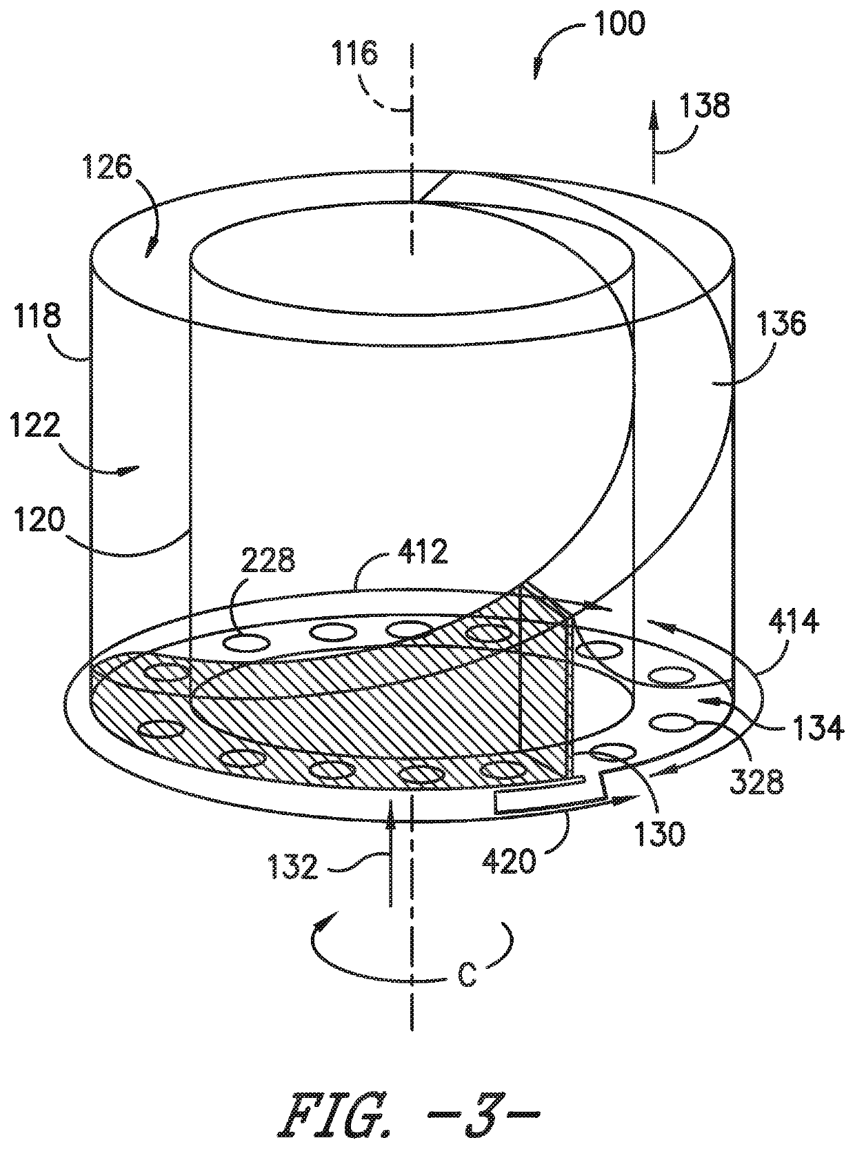
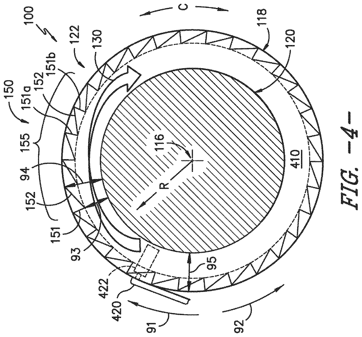
[0032]Reference now will be made in detail to embodiments of the invention, one or more examples of which are illustrated in the drawings. Each example is provided by way of explanation of the invention, not limitation of the invention. In fact, it will be apparent to those skilled in the art that various modifications and variations can be made in the present invention without departing from the scope or spirit of the invention. For instance, features illustrated or described as part of one embodiment can be used with another embodiment to yield a still further embodiment. Thus, it is intended that the present invention covers such modifications and variations as come within the scope of the appended claims and their equivalents.

[0033]As used herein, the terms “first”, “second”, and “third” may be used interchangeably to distinguish one component from another and are not intended to signify location or importance of the individual components.

[0034]The terms “forward” and “aft” refe...


PUM


Abstract

Systems for rotating detonation combustion are provided herein. The system includes an inner wall and an outer wall each extended around a centerline axis, wherein a detonation chamber is defined between the inner wall and the outer wall, and an iterative structure positioned at one or both of the inner wall or the outer wall. The iterative structure includes a first threshold structure corresponding to a first pressure wave attenuation and a second threshold structure corresponding to a second pressure wave attenuation. The iterative structure provides for pressure wave strengthening along a first circumferential direction in the detonation chamber or pressure wave weakening along a second circumferential direction opposite of the first circumferential direction. The first circumferential direction corresponds to a desired direction of pressure wave propagation in the detonation chamber.

Description

FIELD[0001]The present subject matter relates generally to a system for continuous detonation in a heat engine such as a propulsion system.BACKGROUND[0002]Many propulsion systems, such as gas turbine engines, are based on the Brayton Cycle, where air is compressed adiabatically, heat is added at constant pressure, the resulting hot gas is expanded in a turbine, and heat is rejected at constant pressure. The energy above that required to drive the compression system is then available for propulsion or other work. Such propulsion systems generally rely upon deflagrative combustion to burn a fuel / air mixture and produce combustion gas products which travel at relatively slow rates and constant pressure within a combustion chamber. While engines based on the Brayton Cycle have reached a high level of thermodynamic efficiency by steady improvements in component efficiencies and increases in pressure ratio and peak temperature, further improvements are welcomed nonetheless.[0003]According...

Claims


Application Information

Patent Timeline
IPC IPC(8): F23R7/00F23R3/00F23R3/28
CPCF23R7/00F05D2220/10F23R3/28F23R3/002
Inventor SINGH, KAPIL KUMARLAVERTU, THOMAS MICHAELDYSON, THOMAS EARLMONAHAN, SARAH MARIETANGIRALA, VENKAT ESWARLUHAYNES, JOEL MEIER
Owner GENERAL ELECTRIC CO
Learn More