Communication apparatus
a technology of communication apparatus and communication circuit, which is applied in the field of communication circuits, can solve the problems of reducing the transmission power of flying objects, and reducing the transmission distance of signals to other cells, so as to reduce the transmission distance of signals, the effect of suppressing the interference of the mobile terminal corresponding to the flying object and reducing the transmission distan
- Summary
- Abstract
- Description
- Claims
- Application Information
AI Technical Summary
Benefits of technology
Problems solved by technology
Method used
Image
Examples
first embodiment
Modification of First Embodiment
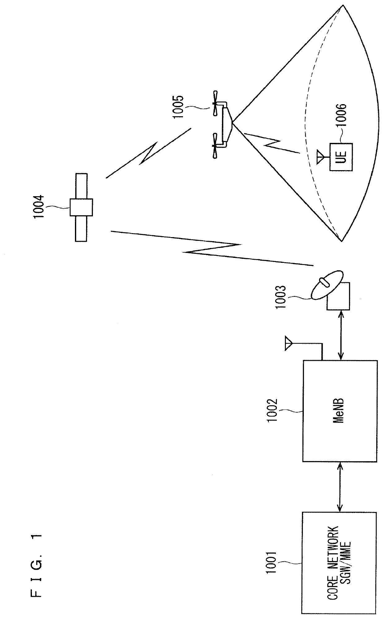
[0135]In the following, a case where the MeNB and SeNB are provided in the flying object is described.
[0136]In a case where a temporary increase of radio traffic or the like is predicted, it is also effective to provide an MeNB and an SeNB in the flying object. At this time, as illustrated in FIG. 5, a connection between the core network and the base station (MeNB+SeNB) is established through a line such as a satellite line, and communication between the flying object including the MeNB and the SeNB and the core network is established. Or, as illustrated in FIG. 6, the connection between the core network and the base station (MeNB+SeNB) is performed using time, frequency, code or space, which is not used in communication with the mobile terminal, and communication between the flying object and the core network is established.
[0137]Here, FIG. 5 is a diagram schematically illustrating a modified example of the configuration of the communication apparatu...
second embodiment
Modification 2 of Second Embodiment
[0214]In a case where the mobile terminal cannot be equipped with a function, such as APAA, for controlling the directivity of the transmission / reception beam or beam width and a simple dipole antenna or patch antenna is installed, controlling the transmission power is effective as a second method.
[0215]When performing a random access, initially establishing communication, or establishing communication with a different base station by handover, the mobile terminal transmits a synchronization known sequence and gradually increases the transmission power before a respond (ACK) is returned from the base station as an apparatus at the other end. Then, as illustrated in FIGS. 14 and 15, when the response (ACK) is returned, the control for increasing the transmission power is stopped. More specifically, until the response (ACK) is returned from the base station, the transmission power at the mobile terminal is increased to 0 dB, +3 dB, +6 dB, and +9 dB, ...
third embodiment
[0218]A communication apparatus according to the present embodiment will be described. In the following description, the same components as those described in the above described embodiment are denoted by the same reference numerals, and detailed description thereof will be omitted as appropriate.
[0219]Hereinafter, an operation in the base station side when the mobile terminal is provided in the flying object or when the flying object itself is the mobile terminal will be described.
[0220]In general, in order to reduce interference with other cells, the base station sets the direction of a transmitting beam downward from the horizontal direction. However, when the mobile terminal is equipped with a flying object, or when the flying object itself is a mobile terminal, in an extreme example, the mobile terminal may be located directly above the base station and the mobile terminal cannot be detected even if the base station has a function to control transmission / reception beam directiv...
PUM
 Abstract
Description
Claims
Application Information
 - R&D
- Intellectual Property
- Life Sciences
- Materials
- Tech Scout
- Unparalleled Data Quality
- Higher Quality Content
- 60% Fewer Hallucinations
Browse by: Latest US Patents, China's latest patents, Technical Efficacy Thesaurus, Application Domain, Technology Topic, Popular Technical Reports.
© 2025 PatSnap. All rights reserved.Legal|Privacy policy|Modern Slavery Act Transparency Statement|Sitemap|About US| Contact US: help@patsnap.com


