Terminal, and mounting structure of terminal and mounting surface

a technology of mounting structure and terminal, which is applied in the direction of vehicle connectors, connection contact parts, electrical equipment, etc., can solve the problems of demerit of background-art terminals, substantially many man-hours for processing mounting holes or mounting parts, and complex shape of mounting parts, etc., to increase man-hours or maintenance costs

Active Publication Date: 2021-04-01
YAZAKI CORP
View PDF0 Cites 0 Cited by
  • Summary
  • Abstract
  • Description
  • Claims
  • Application Information

AI Technical Summary

Benefits of technology

[0005]It is considered that the aforementioned background-art terminal has a merit since it can omit fastening work in comparison with a case where the terminal is fastened to the vehicle body frame by means of a bolt or the like. However, in order to put the terminal to practical use, it is necessary to provide a dedicated mounting hole corresponding to the shape of the mounting member in each earth point of the vehicle body frame of the vehicle. In addition, the mounting member itself has a complicated shape suitable for the aforementioned mounding. Accordingly, substantially many man-hours are required for processing the mounting hole or the mounting member. Further, high-level dimensional accuracy is required in the mounting hole or the mounting member so that a proper value can be kept as the force with which the terminal is pressed against the vehicle body frame (corresponding to fastening torque in a case of fastening with a bolt) in order to secure the reliability of electric connection. Consequently, it is considered that the background-art terminal has a demerit since it can increase the man-hours or the maintenance cost when it is in practical use.

Problems solved by technology

In addition, the mounting member itself has a complicated shape suitable for the aforementioned mounding.
Accordingly, substantially many man-hours are required for processing the mounting hole or the mounting member.
Consequently, it is considered that the background-art terminal has a demerit since it can increase the man-hours or the maintenance cost when it is in practical use.

Method used


Image

  • Terminal, and mounting structure of terminal and mounting surface
  • Terminal, and mounting structure of terminal and mounting surface
  • Terminal, and mounting structure of terminal and mounting surface

Examples


Embodiment Construction

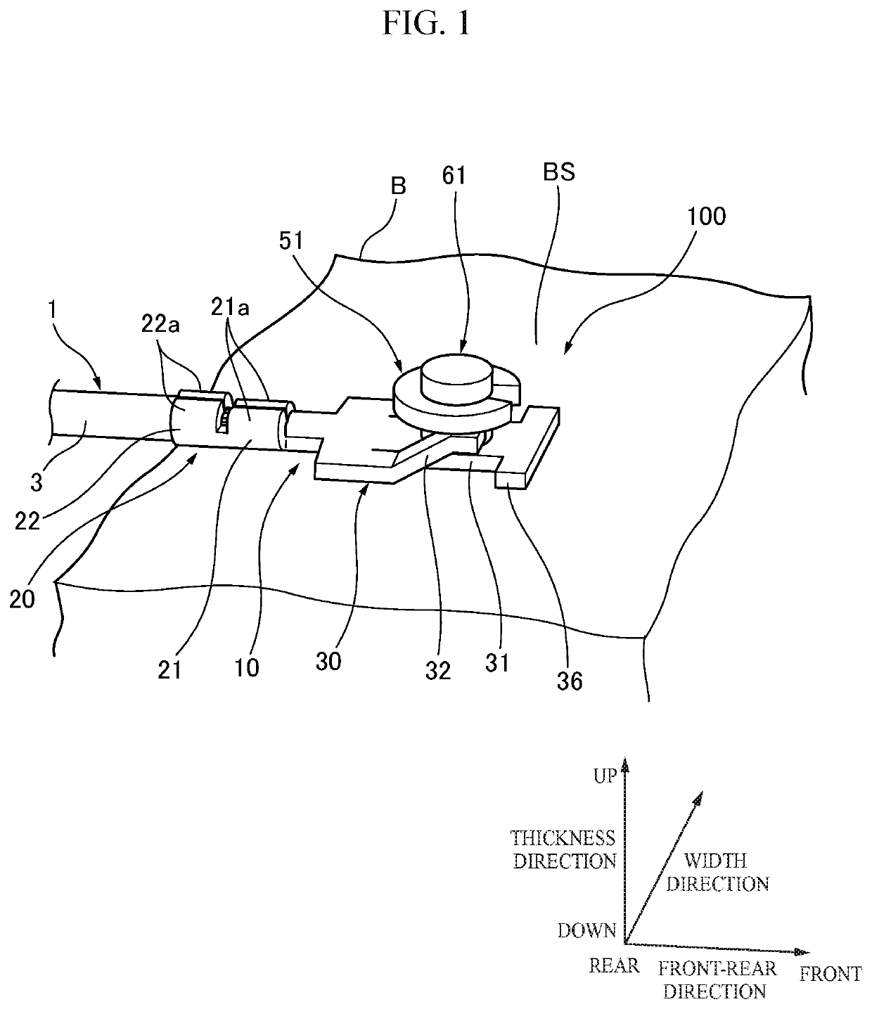
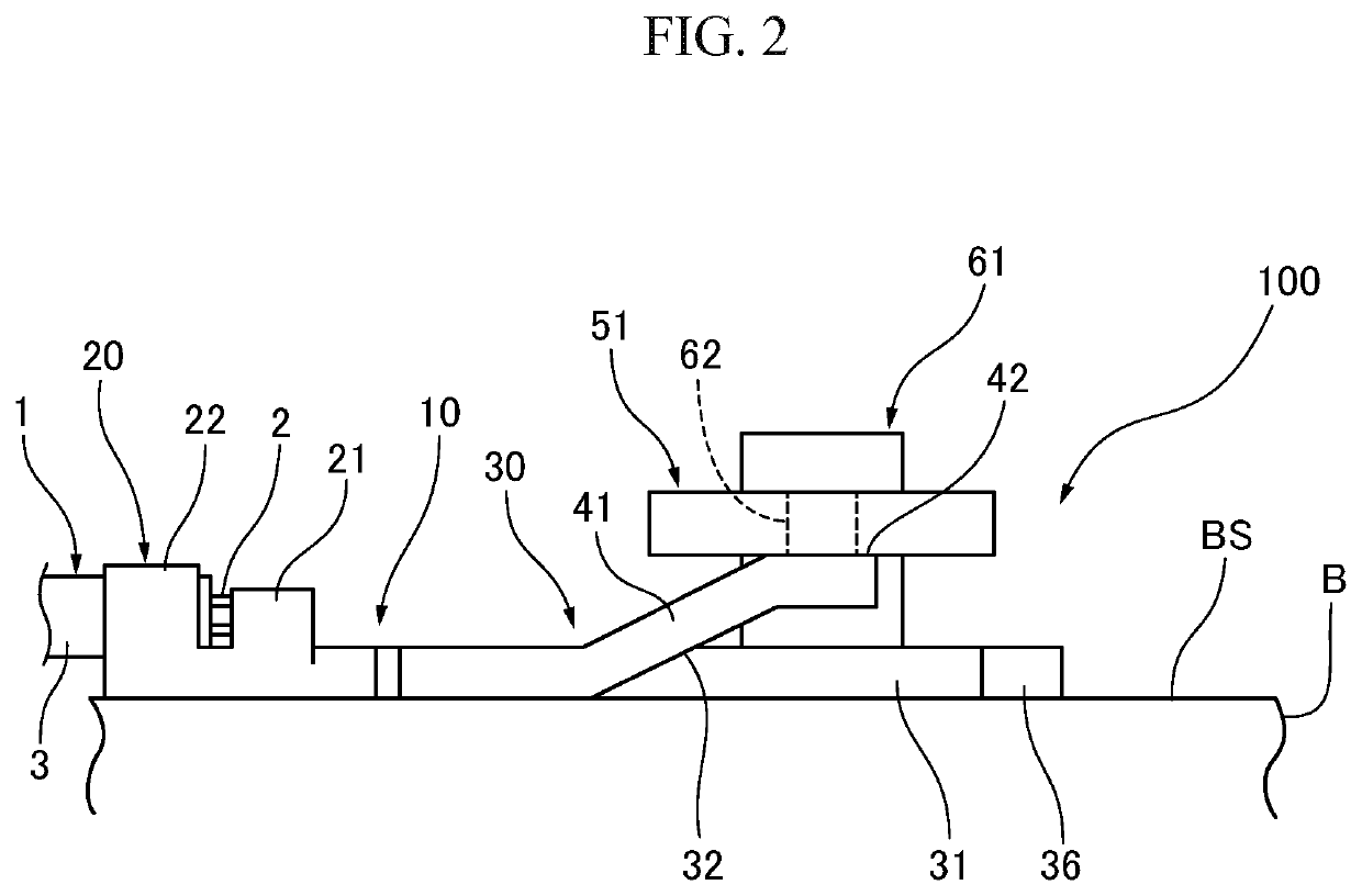
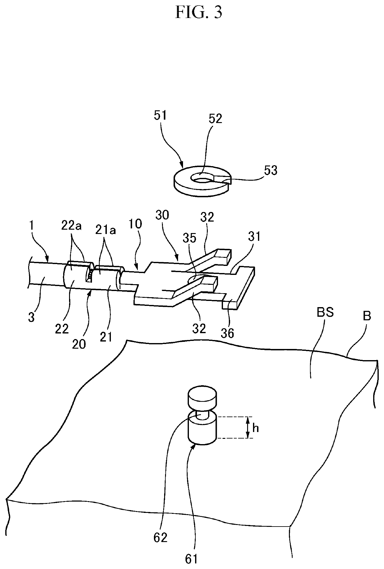
[0021]A terminal 10, and a mounting structure 100 between the terminal 10 and a mounting surface BS will be described below with reference to the drawings. In the following description, for convenience of explanation, “front / rear direction”, “width direction”, “thickness direction”, “front”, “rear”. “left”, “right”, “up” and “down” are defined as shown in the drawings. “Front / rear direction”, “left right direction” and “up / down direction” cross one another.

[0022]As shown in FIG. 1 to FIG. 3, the terminal 10 according to the embodiment is connected to an end portion of an electric wire 1. The terminal 10 is, for example, mounted on a mounting surface BS of a vehicle body frame B of a vehicle such as an automobile so as to secure electric conduction thereto. The electric wire 1 is, for example, a ground wire for grounding various electric parts mounted on the vehicle. That is, the terminal 10 is a ground terminal to which the electric wire 1 for ground has been connected. The terminal...


PUM


Abstract

A terminal is mounted on a mounting surface having a stud bolt standing on the mounting surface. The terminal having: a contact portion configured to contact with the mounting surface; an insertion portion allowing the stud bolt to be inserted to the insertion portion; and an elastic portion connected to the contact portion and extending in a direction to leave the mounting surface. The elastic portion is configured to urge the contact portion elastically toward the mounting surface when he terminal touches a fixture engaged with the stud bolt.

Description

CROSS-REFERENCE TO RELATED APPLICATIONS[0001]This application is based on and claims priority under 35 USC 119 from Japanese Patent Application No. 2019-179433 filed on Sep. 30, 2019, the contents of which are incorporated herein by reference.TECHNICAL FIELD[0002]The present invention relates to a terminal, and a mounting structure between the terminal and a mounting surface.BACKGROUND ART[0003]In the background art, terminals have been proposed in order to be used for grounding various electric parts mounted on a vehicle to a vehicle body frame or the like of the vehicle. For example, one of the terminals in the background art has a contact portion (having a so-called round shape) provided with a through hole. The terminal is disposed so that the through hole is put on top of a mounting hole formed in the vehicle body frame of the vehicle. In this state, the contact portion is pressed against the vehicle body frame by a dedicated mounting member which is inserted into the through h...

Claims


Application Information

Patent Timeline
Patent Type & Authority Applications(United States)
IPC IPC(8): H01R11/12H01R4/64
CPCH01R11/12H01R4/64H01R11/22H01R11/26H01R4/646H01R4/30H01R2201/26
Inventor KATOH, HIROSHIWATANABE, JIN
Owner YAZAKI CORP
Why Eureka
Try Eureka