Cable and medical hollow tube

a hollow tube and cable technology, applied in the direction of insulated conductors, cables, catheters, etc., can solve the problems of protecting members detaching from the cable, and achieve the effects of suppressing the formation of voids, reducing the number of air bubbles, and high adhesion strength

Active Publication Date: 2021-03-18
HITACHI METALS LTD
View PDF0 Cites 3 Cited by
  • Summary
  • Abstract
  • Description
  • Claims
  • Application Information

AI Technical Summary

Benefits of technology

The present invention provides a cable with a coating film that has improved adhesion strength and reduced voids on its surface. The coating film is made of a rubber composition that includes rubber and fine particles. The use of addition reaction type silicone rubber helps to reduce air bubbles during the curing process, ensuring a smooth surface. The adhesion strength between the coating film and the sheath is maintained without the need for a special layer. The coating film can also be formed by a dipping method that promotes the self-ordering of the fine particles and ensures high productivity. Overall, the cable with the coating film has improved performance and durability.

Problems solved by technology

Here, in the cable with the protective member having been attached thereto, for example, when the end portion of the cable is bent, a coating film, which has been formed on a surface of the sheath, may be peeled off, which may lead to the protective member detaching from the cable.

Method used


Image

  • Cable and medical hollow tube
  • Cable and medical hollow tube
  • Cable and medical hollow tube

Examples


example 1

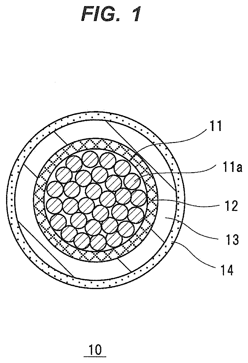
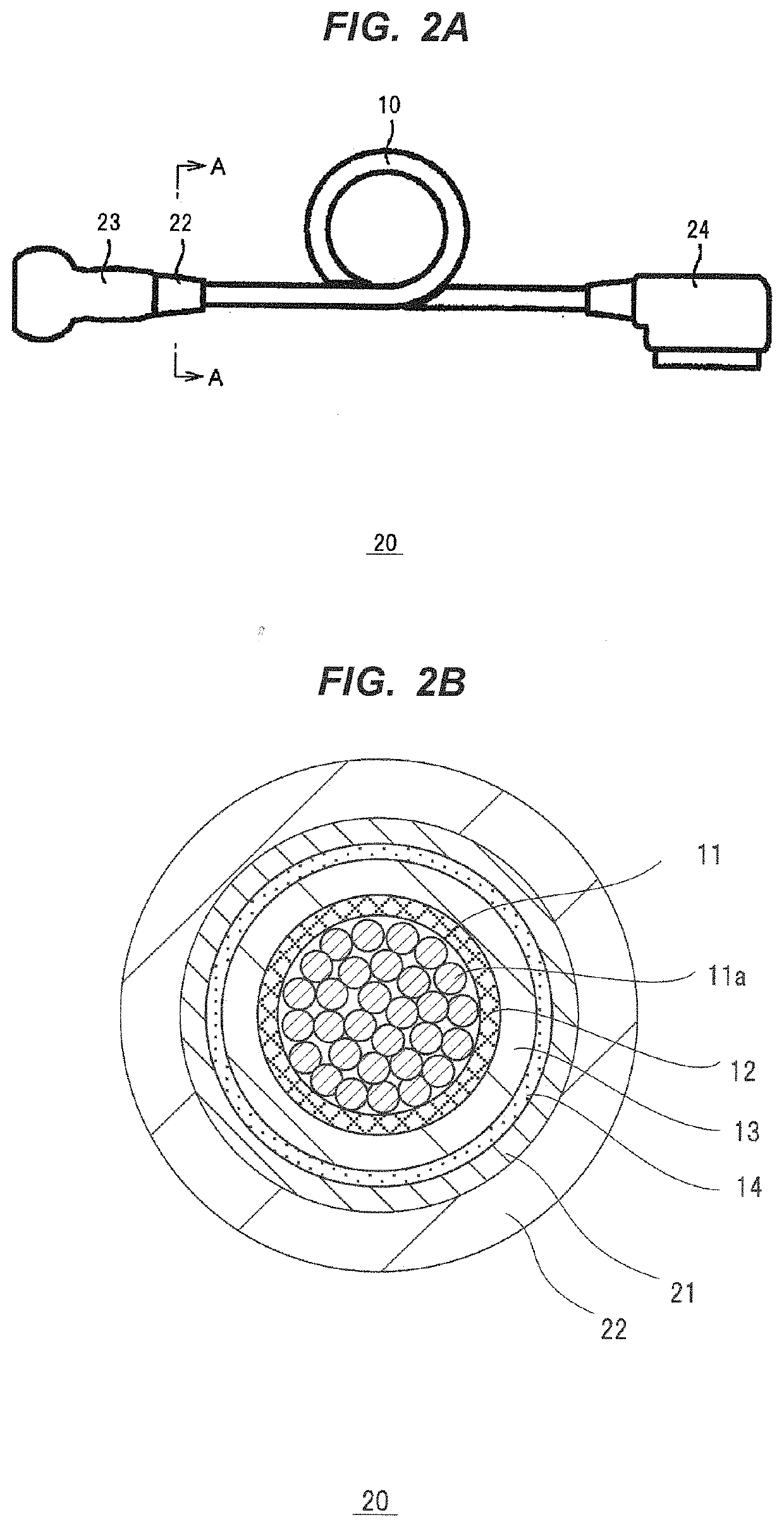
[0123](Production of cable)

[0124]First, laid 200 coaxial cables each having a diameter of about 0.25 mm were coated with a braided wire to produce a cable core (the cable core 11). Subsequently, a sheath material was extruded at a rate of 5 m / min using an extruder to coat an outer periphery of the cable core, on which was formed a sheath having a thickness of 0.8 mm (cable outer diameter: about 8 mm). A silicone rubber (“KE-541-U” available from Shin-Etsu Chemical Co., Ltd.) was used as the sheath material.

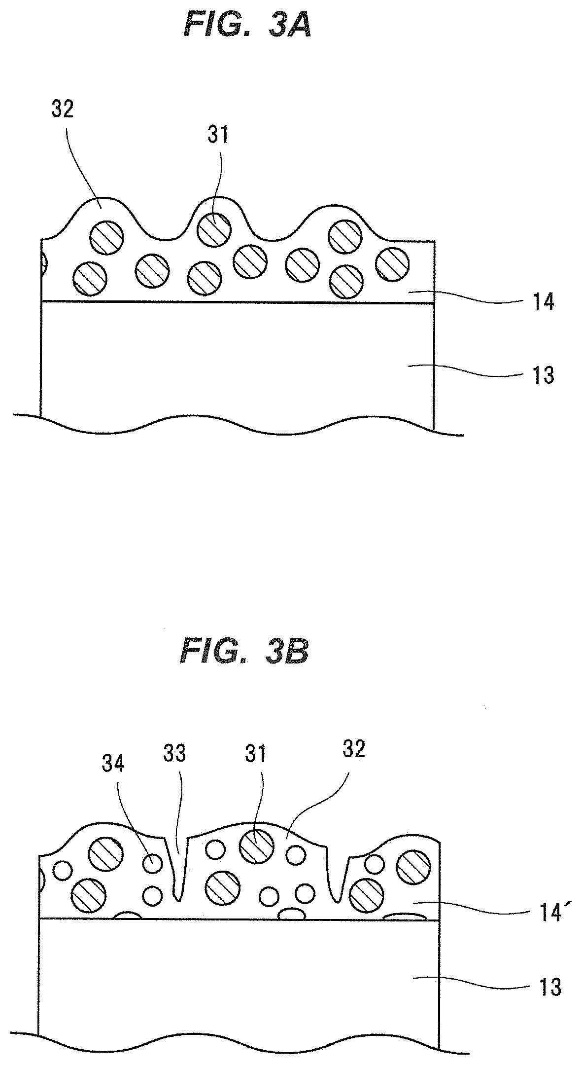
[0125]Subsequently, materials to form a coating film (the coating film 14) were compounded. In Example 1, as a rubber component to compose the coating film, an addition reaction type silicone rubber coating agent (trade name: SILMARK-TM, available from Shin-Etsu Chemical Co., Ltd.) was prepared, and as fine particles to compose the coating film, silicone resin fine particles having an average particle diameter of 5 gm (trade name: X-52-1621, available from Shin-Etsu Chemical Co., ...

example 2

[0128]In Example 2, a coating solution was compounded and a cable was produced in the same manner as in Example 1 except that the silicone rubber resin particles content was changed from 120 parts by mass to 150 parts by mass, and the proportion of the silicone resin fine particles to the coating film was changed to 60.0% by mass.

example 3

[0129]In Example 3, a coating solution was compounded and a cable was produced in the same manner as in Example 1 except that the fumed silica was not added.


PUM

PropertyMeasurementUnit
lengthaaaaaaaaaa
lengthaaaaaaaaaa
particle diameteraaaaaaaaaa

Abstract

A cable includes a sheath, and a coating film covering a circumference of the sheath, the coating film adhering to the sheath. The coating film is formed from a rubber composition including a rubber component and fine particles. A static friction coefficient on a surface of the coating film is 0.5 or less. When the coating film is subjected to a testing such that a long fiber non-woven fabric including cotton linters including an alcohol for disinfection with a length of 50 mm along a wiping direction is brought contiguous to the surface of the coating film at a shearing stress of 2×10⁻³ MPa to 4×10⁻³ MPa, followed by wiping off the surface of the coating film at a speed of 80 times / min to 120 times / min and 20,000 repetitions thereof for a wiping direction length of 150 mm, a difference (an absolute value of a difference) between the static friction coefficients of the coating film before and after the testing is not greater than 0.1.

Description

CROSS-REFERENCE TO RELATED APPLICATION[0001]The present application is based on Japanese patent application No.2019-167722 filed on Sep. 13, 2019 and Japanese patent application No.2020-031580 filed on Feb. 27, 2020, the entire contents of which are incorporated herein by reference.BACKGROUND OF THE INVENTION1. Field of the Invention[0002]The present invention relates to a cable and a medical hollow tube.2. Description of the Related Art[0003]JP-A-2008-287 (Patent Document 1) and JP-A-2018-23758 (Patent Document 2) discloses a technique on a medical coating composition, which can impart a stable sliding property to a surface without applying a lubricant to that surface.[0004][Patent Document 1] JP-A-2008-287[0005][Patent Document 2] JP-A-2018-23758SUMMARY OF THE INVENTION[0006]A sheath made of an electrical insulating member is formed on a surface of a cable. This sheath is desired to have no stickiness or the like, but a good slidability (sliding property). On the other hand, an en...

Claims


Application Information

Patent Timeline
Patent Type & Authority Applications(United States)
IPC IPC(8): C09D183/04C09D7/40C09D7/61C09D7/65A61M25/00H01B7/18H01B3/46
CPCC09D183/04C09D7/69C09D7/61A61M2025/0046A61M25/0045H01B7/18H01B3/46C09D7/65H01B7/17H01B7/02H01B7/041H01B3/28A61B8/44A61B18/1492A61L29/085C08L83/04A61B8/56A61M25/005A61L29/14H01B7/048H01B7/0208A61B2562/222A61L2400/10A61B1/00064A61L2420/04C08K3/36B32B3/30
Inventor KASHIMURA, SEIICHIKISHI, MASAMICHITERAKI, NAOTOWATANABE, TAKANOBUKIYOKANE, YURIKO
Owner HITACHI METALS LTD
Why Eureka
Try Eureka