
A system and method for manufacturing a reinforced wind turbine blade

a wind turbine and reinforced technology, applied in the field of system and method for manufacturing a reinforced wind turbine blade, can solve the problems of high-quality blade moulds, high cost of blade moulds in use, and considerable cost and lead time in the implementation of a manufacturing process for a new wind turbine blade. , to achieve the effect of improving the stability of the resulting wind turbine blade, flexible and effective moulding, and saving time and cos

Active Publication Date: 2021-03-18
LM WIND POWER INT TECH II APS
View PDF0 Cites 1 Cited by
  • Summary
  • Abstract
  • Description
  • Claims
  • Application Information

AI Technical Summary

Benefits of technology

The present invention provides a method for manufacturing wind turbine blades using cradles that allow for faster production and better support of the blade. This method also allows for a quicker and more efficient manufacture, resulting in increased production per mold. The closing mechanism is used to bond the blade shells together to form the finished wind turbine blade. The reinforcing station can be either local or remote from the blade molds, and preferably includes the closing mechanism. Overall, the method improves the efficiency of wind turbine blade production.

Problems solved by technology

High-quality blade moulds are one of the most expensive pieces of equipment in the blade manufacturing process, requiring extensive tooling and manufacture before use to ensure accurate reproduction of desired blade profiles, as well as to allow for the turning of the moulds to bond blade shell parts together.
Blade moulds in use in current processes can cost approximately €1-3 million to manufacture and, dependent on where the moulds are made, extensive transportation time may be a factor before a new mould can be used at a manufacturing plant.
This introduces considerable expense and lead time in the implementation of a manufacturing process for a new wind turbine blade.
Accordingly, one of the limitations to efficient implementation of wind turbine technology is the time required for the initial setup of a blade manufacturing system.
A further limitation is the time taken for the manufacturing of individual blades within such a system.
It has been found by the present inventors that such prior art systems and methods present certain limitations, in particular when using a two-step infusion process in which different blade elements, such as reinforced structures like spar caps or main laminates, are moulded and infused subsequent to a first moulding and infusion of another blade element.

Method used


Image

  • A system and method for manufacturing a reinforced wind turbine blade
  • A system and method for manufacturing a reinforced wind turbine blade
  • A system and method for manufacturing a reinforced wind turbine blade

Examples


Embodiment Construction

[0087]Certain embodiments of the invention will now be described, by way of example only, with reference to the accompanying drawings, in which:

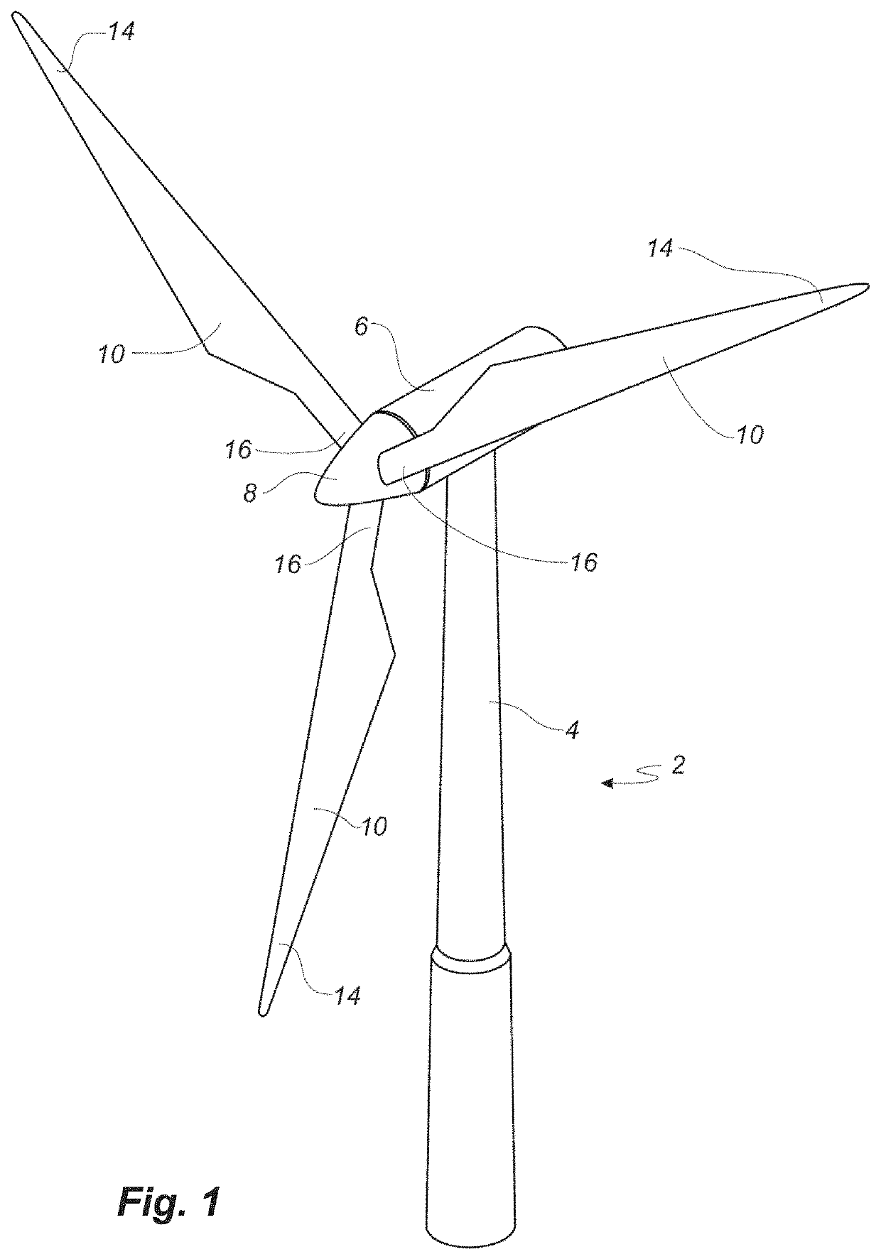
[0088]FIG. 1 shows a wind turbine;

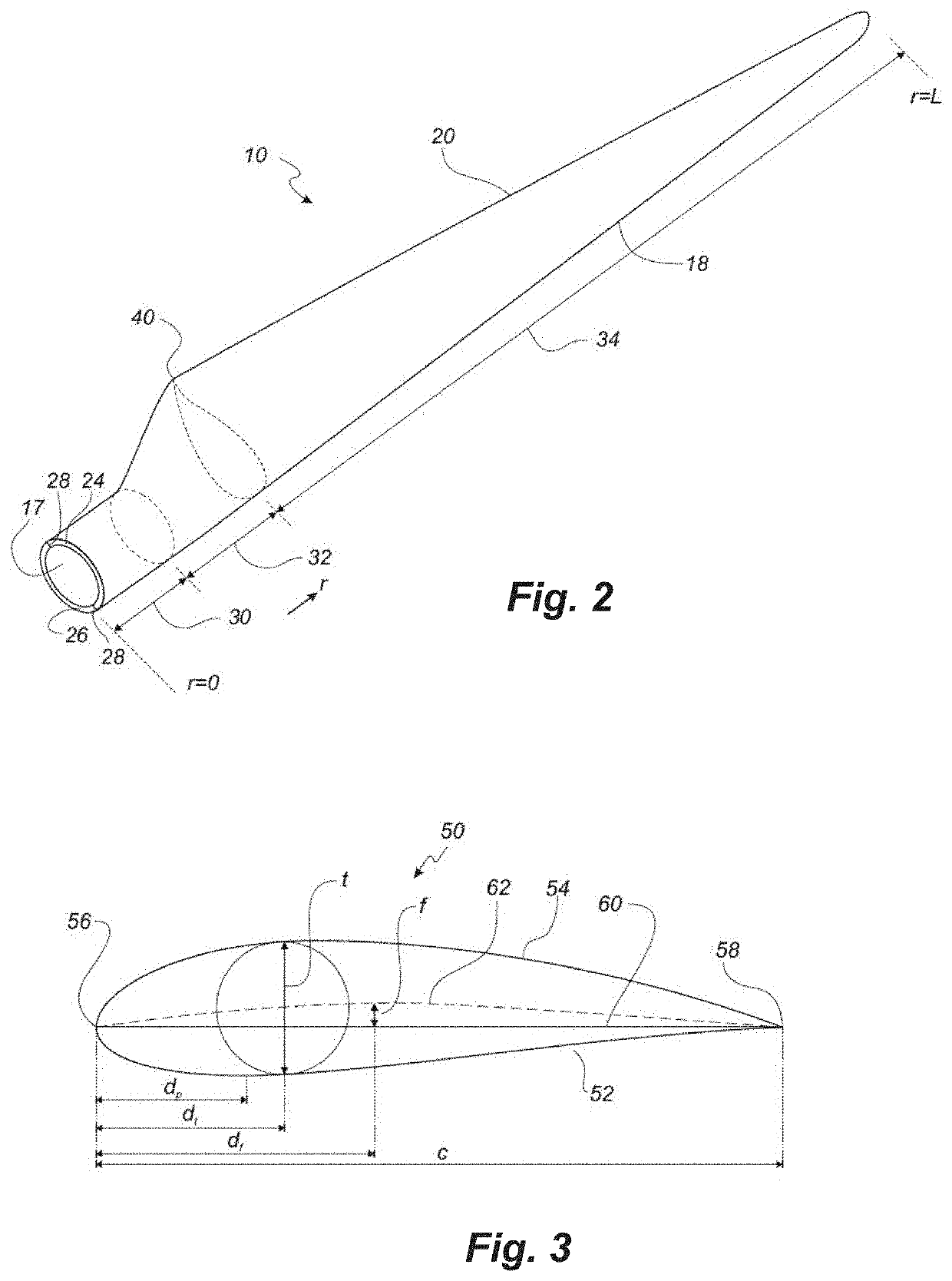
[0089]FIG. 2 shows a schematic view of a wind turbine blade;

[0090]FIG. 3 shows a schematic view of an airfoil profile of the blade of FIG. 2;

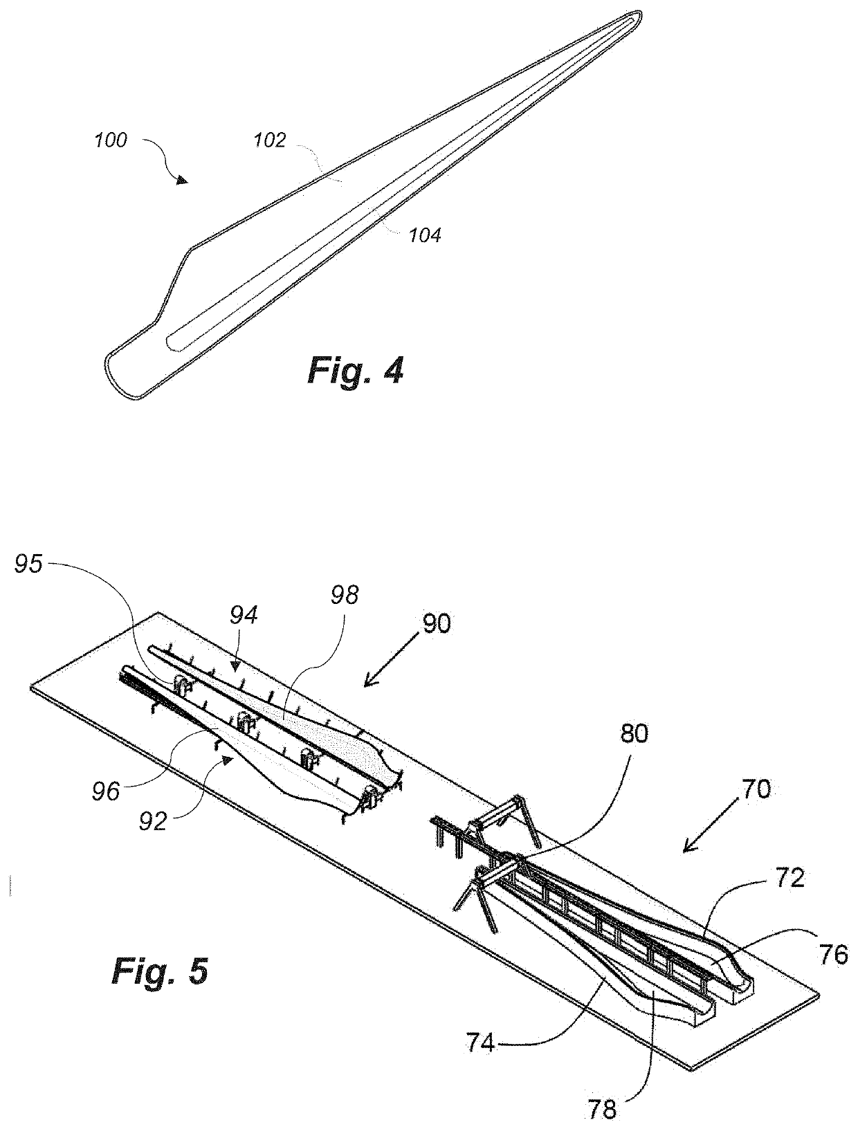
[0091]FIG. 4 is a perspective view of a blade shell manufactured using the method of the present invention comprising a cured blade element and a reinforced section;

[0092]FIG. 5 is a perspective view of a manufacturing system according to the present invention,

[0093]FIG. 6 is a perspective view of a mould body according to the present invention,

[0094]FIG. 7 is a partial, enlarged view of a mould body according to the present invention,

[0095]FIG. 8 is a partial, sectional view of a mould body according to the present invention,

[0096]FIG. 9 is a perspective view of another embodiment of a mould body according to the present invention,

[0097]FIG. 10 is a perspective view of...


PUM


Abstract

The present invention relates to a method and system for manufacturing a wind turbine blade. The method comprising the steps of forming a cured blade element (102) of a first blade shell, forming a cured blade element (102) of a second blade shell, transferring the cured blade element (102) of the first blade shell to a first cradle (92), and transferring the cured blade element (102) of the second blade shell to a second cradle (94). Each cradle comprises a mould body (96, 98) having a moulding surface for abutting against a surface of the cured blade element to advantageously form a seal therebetween.

Description

FIELD OF THE INVENTION[0001]The present invention relates to a system and method for manufacturing a reinforced wind turbine blade, as well as to a wind turbine blade obtainable by said method.BACKGROUND OF THE INVENTION[0002]Wind turbine blades are typically manufactured using first and second blade shells, moulded in a pair of adjacent blade moulds. First, a blade gel coat or primer is typically applied to the blade mould. Subsequently, fibre reinforcement and / or fabrics are placed into the mould followed by resin infusion. A vacuum is typically used to draw epoxy resin material into a mould. Alternatively, prepreg technology can be used, in which a fibre or fabric pre-impregnated with resin forms a homogenous material which can be introduced into the mould.[0003]Once the blade shells have sufficiently cured, the vacuum bags are removed and further operations can be performed on the hardened shells. For example, blade laminates and / or webs can be installed in the blade shells, var...

Claims


Application Information

Patent Timeline
IPC IPC(8): B29D99/00B29C70/44F03D1/06
CPCB29D99/0028B29L2031/085F03D1/0675B29C70/443Y02E10/72Y02P70/50B29C70/541
Inventor JESPERSEN, KLAVSNIELSEN, LARS
Owner LM WIND POWER INT TECH II APS
Learn More