
System and method for analysis of current and voltage levels within a center pivot irrigation system

a technology of current and voltage level analysis and irrigation system, which is applied in the field of system and method for analyzing current and voltage levels of drive towers, can solve the problems of difficult maintenance and monitoring of the drive control system of modern irrigation machines, time-consuming and often inaccurate process, and the status of individual drive wheels often requires physical inspection

Pending Publication Date: 2021-03-18
VALMONT INDUSTIES INC
View PDF16 Cites 3 Cited by
  • Summary
  • Abstract
  • Description
  • Claims
  • Application Information

AI Technical Summary

Benefits of technology

The present invention provides a system and method for analyzing drive tower current and voltage levels to determine drive wheel status. The machine analysis module applies a current sensing algorithm that analyzes the status of selected drive wheels based on the detected electrical current / voltage levels of selected motors using a movement rate algorithm, field location algorithm, and distance analysis algorithm. The invention helps to improve the efficiency and accuracy of analyzing the status of drive wheels, which can be useful in various applications such as agricultural machines and construction equipment.

Problems solved by technology

The drive control systems of modern irrigation machines are difficult to maintain and monitor.
In particular, the status of individual drive wheels often requires physical inspection and monitoring during irrigation operations.
This process is time consuming and often inaccurate.
Even when closely monitored, it is difficult to assess the actual performance of each drive wheel independent from the loads applied to each wheel and the field conditions for each drive wheel path.
Because of this, operators often lack good data regarding the actual field conditions for each drive path.
In addition, the operators have no way to analyze or understand variations in drive motor current and voltage readings.

Method used


Image

  • System and method for analysis of current and voltage levels within a center pivot irrigation system
  • System and method for analysis of current and voltage levels within a center pivot irrigation system
  • System and method for analysis of current and voltage levels within a center pivot irrigation system

Examples


Embodiment Construction

[0020]For the purposes of promoting an understanding of the principles of the present invention, reference will now be made to the embodiments illustrated in the drawings and specific language will be used to describe the same. It will nevertheless be understood that no limitation of the scope of the present invention is hereby intended and such alterations and further modifications in the illustrated devices are contemplated as would normally occur to one skilled in the art.

[0021]The terms “program,”“computer program,”“software application,”“module” and the like as used herein, are defined as a sequence of instructions designed for execution on a computer system. A program, computer program, module or software application may include a subroutine, a function, a procedure, an object implementation, an executable application, an applet, a servlet, a source code, an object code, a shared library, a dynamic link library and / or other sequence of instructions designed for execution on a ...


PUM


Abstract

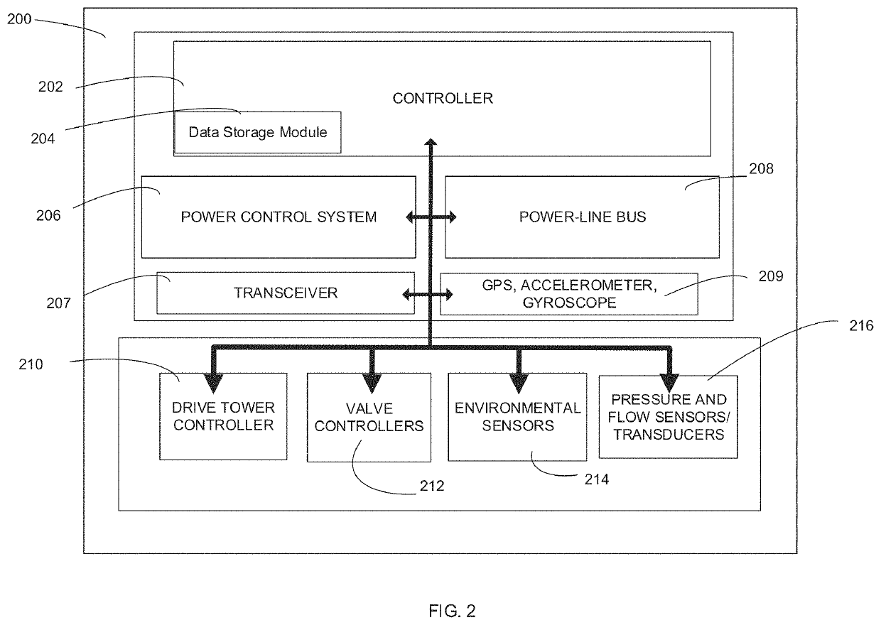
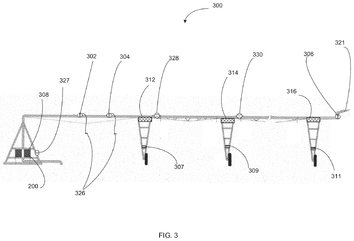
The present invention provides a system and method for analyzing drive tower current and voltage levels to determine drive wheel status. In accordance with a first preferred embodiment, the system of the present invention includes a machine analysis module which analyzes data from electrical sensing systems, GPS sensors, and gyroscopic sensors. According to a further preferred embodiment, the machine analysis module applies a current / voltage sensing algorithm which analyzes the status of the first and second drive wheels based on detected operating currents / voltages of selected motors.

Description

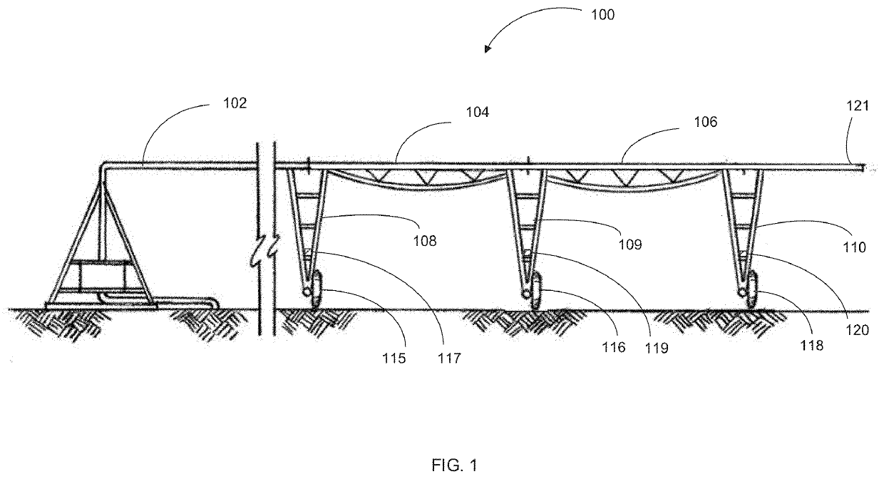
RELATED APPLICATIONS[0001]The present application claims priority to U.S. Provisional Application No. 62 / 899,174 filed Sep. 12, 2019.BACKGROUND AND FIELD OF THE PRESENT INVENTIONField of the Present Invention[0002]The present invention relates generally to a system and method for irrigation system management. More specifically, the present invention relates to a system and method for analyzing drive tower current and voltage levels to determine drive wheel status.BACKGROUND OF THE INVENTION[0003]Modern center pivot and linear irrigation systems generally include interconnected spans (e.g., irrigation spans) supported by one or more tower structures to support the conduits (e.g., water pipe sections). In turn, the conduits are further attached to sprinkler / nozzle systems which spray water (or other applicants) in a desired pattern. In these modern irrigation systems, a significant number of powered elements are used to control various aspects of irrigation. These often include remote...

Claims


Application Information

Patent Timeline
Patent Type & Authority Applications(United States)
IPC IPC(8): A01G25/16A01G25/09
CPCA01G25/16A01G25/092
Inventor THATCHER, TRACY A.
Owner VALMONT INDUSTIES INC
Learn More