Position indicating device and spatial position indicating system

a technology which is applied in the field of position indicating device and spatial position indicating system, can solve the problems of no small position sensor that can be installed in the pen tip, cannot be used in virtual reality space, and gives the user a feeling of strangeness

Active Publication Date: 2021-03-11
WACOM CO LTD
View PDF0 Cites 1 Cited by
  • Summary
  • Abstract
  • Description
  • Claims
  • Application Information

AI Technical Summary

Benefits of technology

[0013]With the position indicating device and the spatial position indicating system according to one aspect of the present disclosure, the force sense generator of the position indicating device (or the electronic pen) is caused to generate a force sense not based on the position of the position indicating device (or the electronic pen) indicated by position information but based on the position of the pen tip. This configuration can, therefore, cause the force sense generator to generate a force sense without giving a feeling of strangeness to the user who is using the electronic pen in the virtual reality space.

Problems solved by technology

In the past, this type of electronic pen has been unable to be used in the virtual reality space.
However, a position sensor for detecting the position of the electronic pen has a certain size, and at least at this point in time, there is no small position sensor available that can be installed in the pen tip.
This gives the user a feeling of strangeness.

Method used


Image

  • Position indicating device and spatial position indicating system
  • Position indicating device and spatial position indicating system
  • Position indicating device and spatial position indicating system

Examples


first embodiment

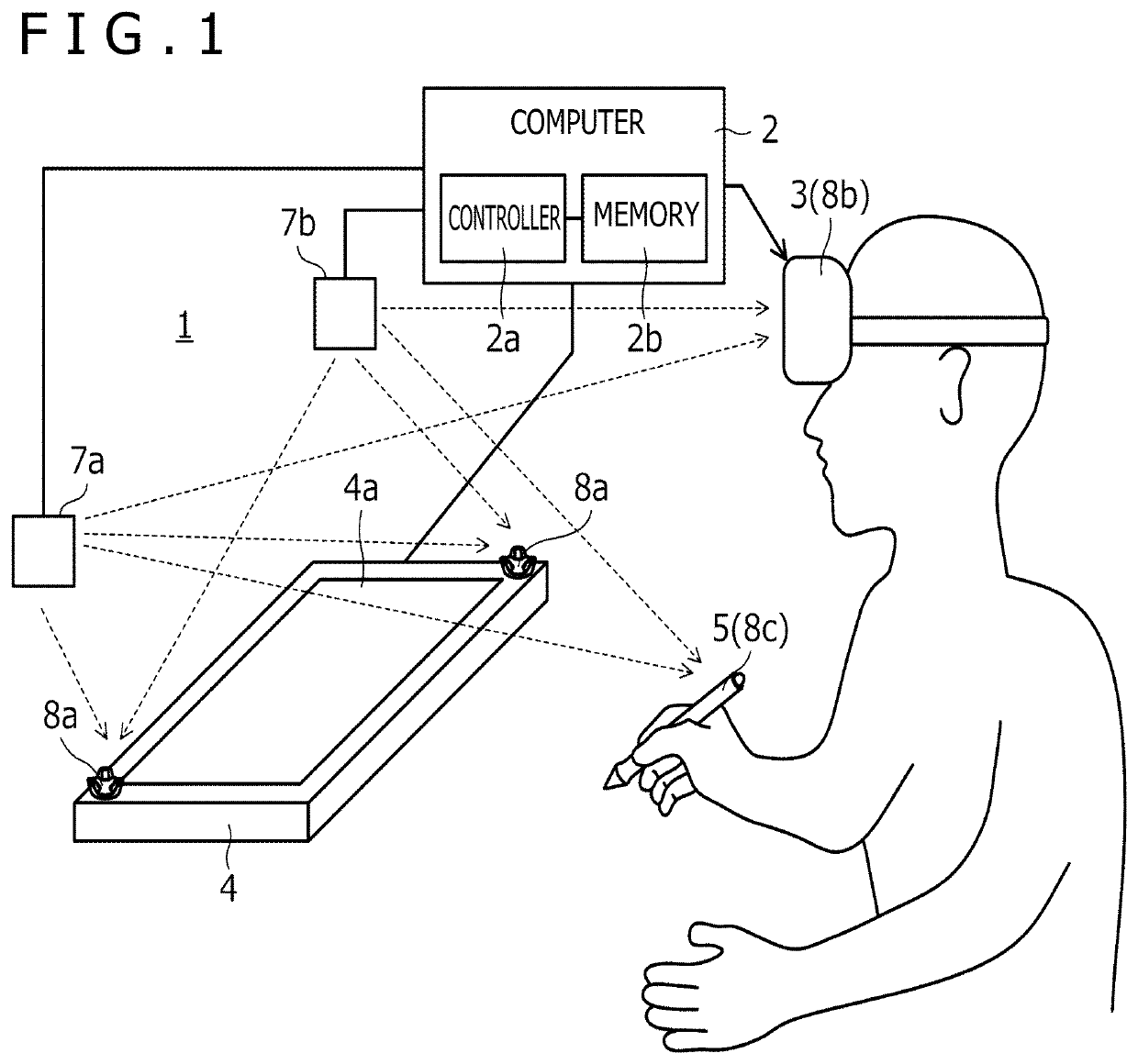
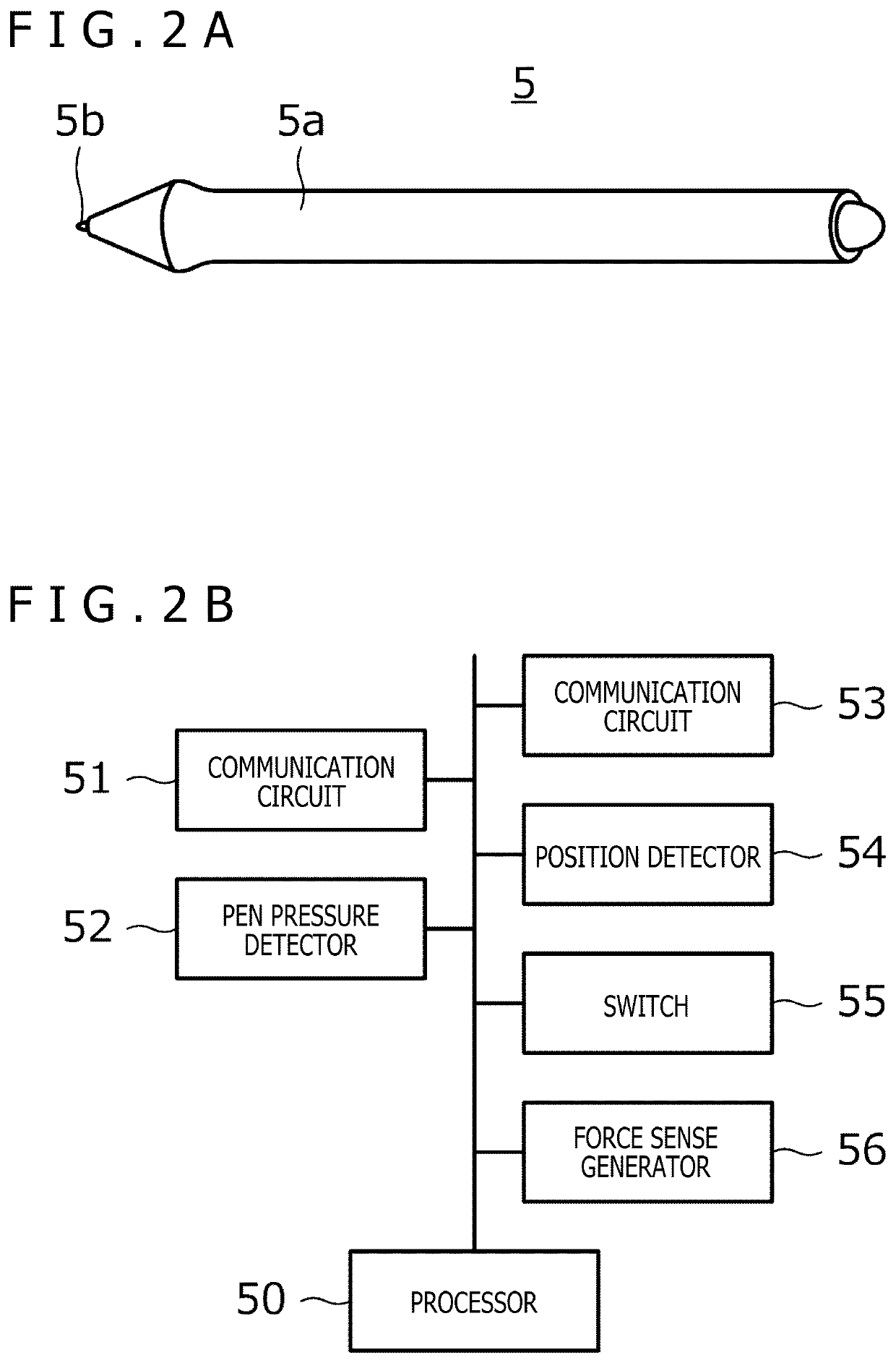
[0030]FIG. 1 is a diagram illustrating a configuration of a spatial position indicating system 1 according to the present disclosure. As illustrated in FIG. 1, the spatial position indicating system 1 according to the present embodiment includes a computer 2, a virtual reality display 3, a tablet 4, an electronic pen 5, lightning houses 7a and 7b, and position sensors 8a to 8c. The position sensors 8a to 8c are provided in the tablet 4, the virtual reality display 3, and the electronic pen 5, respectively.

[0031]In principle, each device illustrated in FIG. 1 is provided in a room. In the spatial position indicating system 1, almost the entire room can be used as a virtual reality space.

[0032]The computer 2 includes a controller 2a (e.g., a processor) and a memory 2b. Each processing operation performed by the computer 2 described below can be performed by the controller 2a reading and executing a program stored in the memory 2b.

[0033]The computer 2 is connected to each of the virtu...

second embodiment

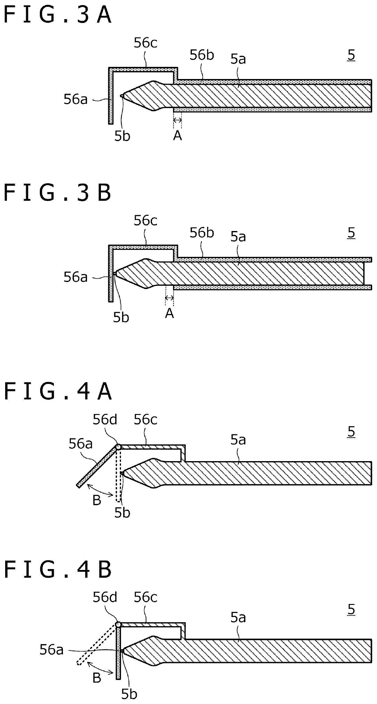
[0114]In the example described in the second embodiment above, the force sense generator 56 includes the abutment portion 56a. Alternatively, the housing 6a or the handle 6b may be provided with the mechanism similar to the one given in the examples illustrated in FIGS. 6 to 8B to configure the force sense generator 56.

[0115]In the examples described in the embodiments above, the control signal for activating the force sense generator 56 is generated in the computer 2. Alternatively, this control signal may be generated in the electronic pen 5 or the spatial position indicating device 6. Hereinafter, processing performed by the processor 50 illustrated in FIG. 2B when the electronic pen 5 is configured in this manner will be described with reference to FIG. 15. The same applies to a case where the control signal is generated in the spatial position indicating device 6, except that the processor 50 illustrated in FIG. 14B performs the processing instead of the processor 50 illustrate...


PUM


Abstract

A position indicating device includes a housing in which an electronic pen including a pen tip is mountable, a force sense generator configured to generate a force sense, and a processor configured to control the force sense generator to generate the force sense when, with the electronic pen mounted in the housing, a distance between a position of the pen tip of the electronic pen in a virtual reality space and an object in the virtual reality space is equal to or less than a predetermined value.

Description

BACKGROUNDTechnical Field[0001]The present disclosure relates to a position indicating device and a spatial position indicating system, and particularly, to a position indicating device and a spatial position indicating system that support haptics.Background Art[0002]There is a technology for writing a character and drawing a picture on a virtual plane in a virtual reality (including virtual reality (VR), augmented reality (AR), and mixed reality (MR)) space. For example, “Tilt Brush” described in “VR Oekaki Apuri ‘Tilt Brush’ Toha? Tsukaikata / Kounyu Houhou mo Shokai” (“What is VR Drawing App ‘Tilt Brush?’ A Guide to How to Use and Purchase It”), [online], MoguraVR, [retrieved on Feb. 28, 2018], Internet <URL: http: / / www.moguravr.com / vr-tilt-brush / > enables the user to draw a picture in the air in a virtual reality space by using a dedicated controller. U.S. Pat. No. 8,884,870 discloses a game in which the user can use a virtual marker, paintbrush, and paint spray-can to creat...

Claims


Application Information

Patent Timeline
Patent Type & Authority Applications(United States)
IPC IPC(8): G06F3/0354G06F3/01
CPCG06F3/03545G06F3/016G06F3/011G06F3/0325G06F3/017G06F3/04162
Inventor IDE, YUICHITAMANO, HIROSHI
Owner WACOM CO LTD
Why Eureka
Try Eureka