Pressure Control Device for a Fluid Dispensing Container

a technology of pressure control device and fluid dispensing container, which is applied in the direction of liquid/fluent solid measurement, volume measurement, application, etc., can solve the problems of pressure control device, commercial product availability, and inability to realize commercial products, etc., and achieve the effect of reducing the total usable space in the bottle and facilitating implementation

Inactive Publication Date: 2008-09-11
I P S RES & DEV
View PDF6 Cites 0 Cited by
  • Summary
  • Abstract
  • Description
  • Claims
  • Application Information

AI Technical Summary

Benefits of technology

[0010]A main advantage of the present invention is that the pressure control device can be pressurized after implementation and filling of the liquid dispensing bottle. This means that the pressure control device may be pressurized at the same time as the bottle of fluid container is filled. Thus there is no need to pressurize the device in advance as was necessary with previous pressure control devices as e.g. described above. Since the second chamber is encompassing the first chamber, a very compact pressure control device will be obtained so that the total usable space in the bottle is much larger as in known embodiments. As the pressure control device can be fabricated in advance and can be implemented easily in existing plastic bottles, the existing production and filling procedures for e.g. cosmetic products can be maintained with only little additional arrangements in the production line.
[0011]Further advantages of the invention are disclosed in the dependent claims and in the following description in which an exemplified embodiment of the invention is described with respect to the accompanying drawings. It shows

Problems solved by technology

Containers with pressure control devices are known in patent literature since almost thirty years but until today no commercial products are available on the market.
Many different embodiments of the device are described, but in practice none was realized in commercial scale.
However, the design of the pressure control device is disadvantageous because of its large dimensions so that less of the container can be used for dispensing fluid.
A further important problem of the above described pressure control devices as a separate module is that the first and second chambers have to be pressurized before mounting in a container.
This in practice may be very difficult and costly to achieve e.g. in aluminium aerosol cans where the construction is in one-piece and the production lines run at very high outputs.
A further major disadvantage is that it has been shown that the pressure in a separate pressure control device which will be mounted afterwards in a container drops to a large extent during a period of some months which is necessary for storage and distribution in the commercial supply chain.
Thus the known pressure control devices are not suitable for application in a large industrial scale.

Method used


Image

  • Pressure Control Device for a Fluid Dispensing Container
  • Pressure Control Device for a Fluid Dispensing Container
  • Pressure Control Device for a Fluid Dispensing Container

Examples


Embodiment Construction

[0017]Specific numbers dedicated to elements defined with respect to a particular figure will be used consistently in all figures if not mentioned otherwise.

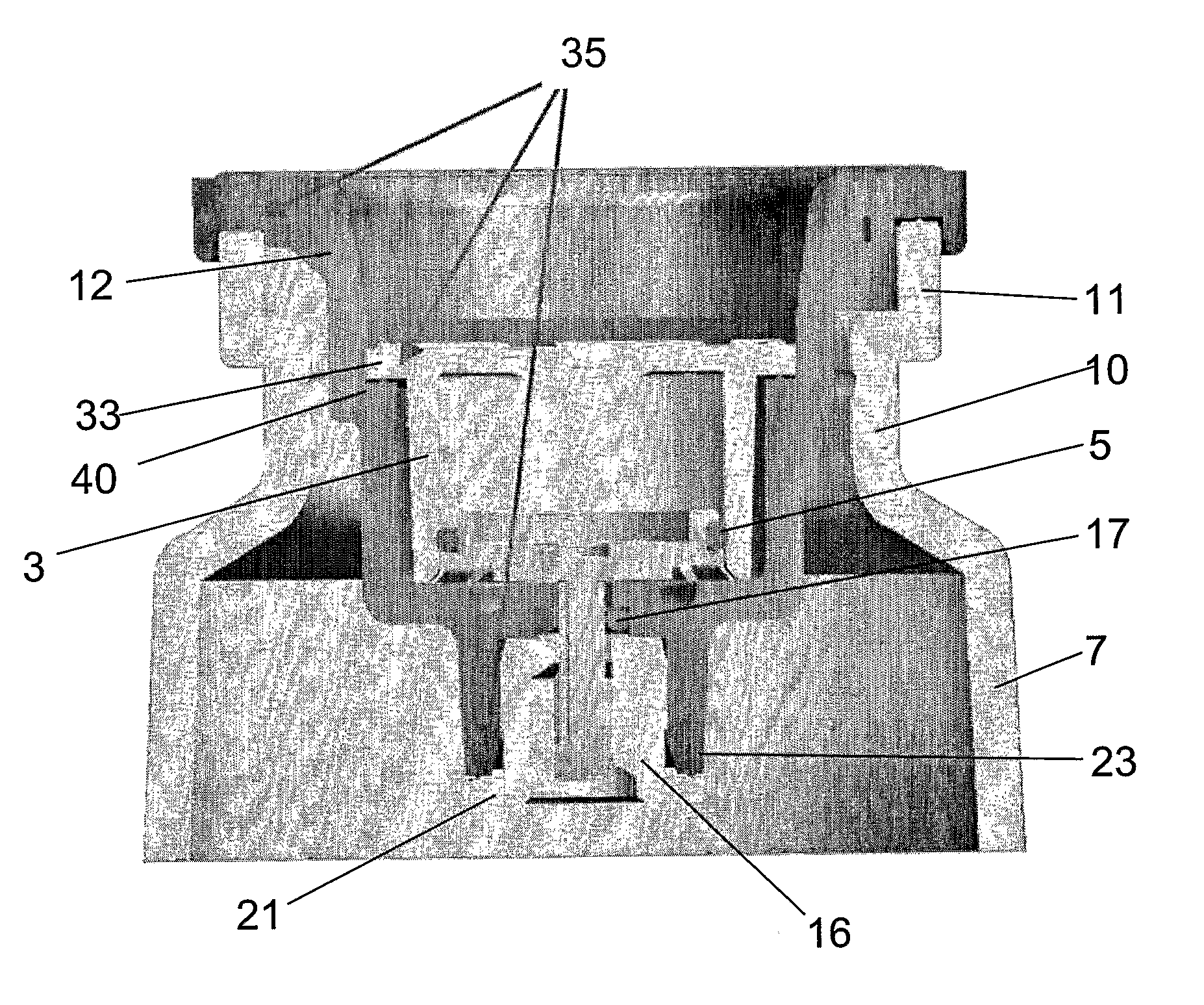
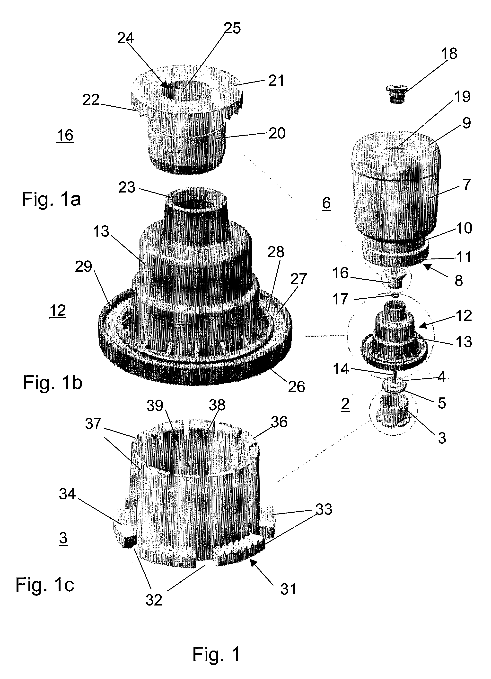
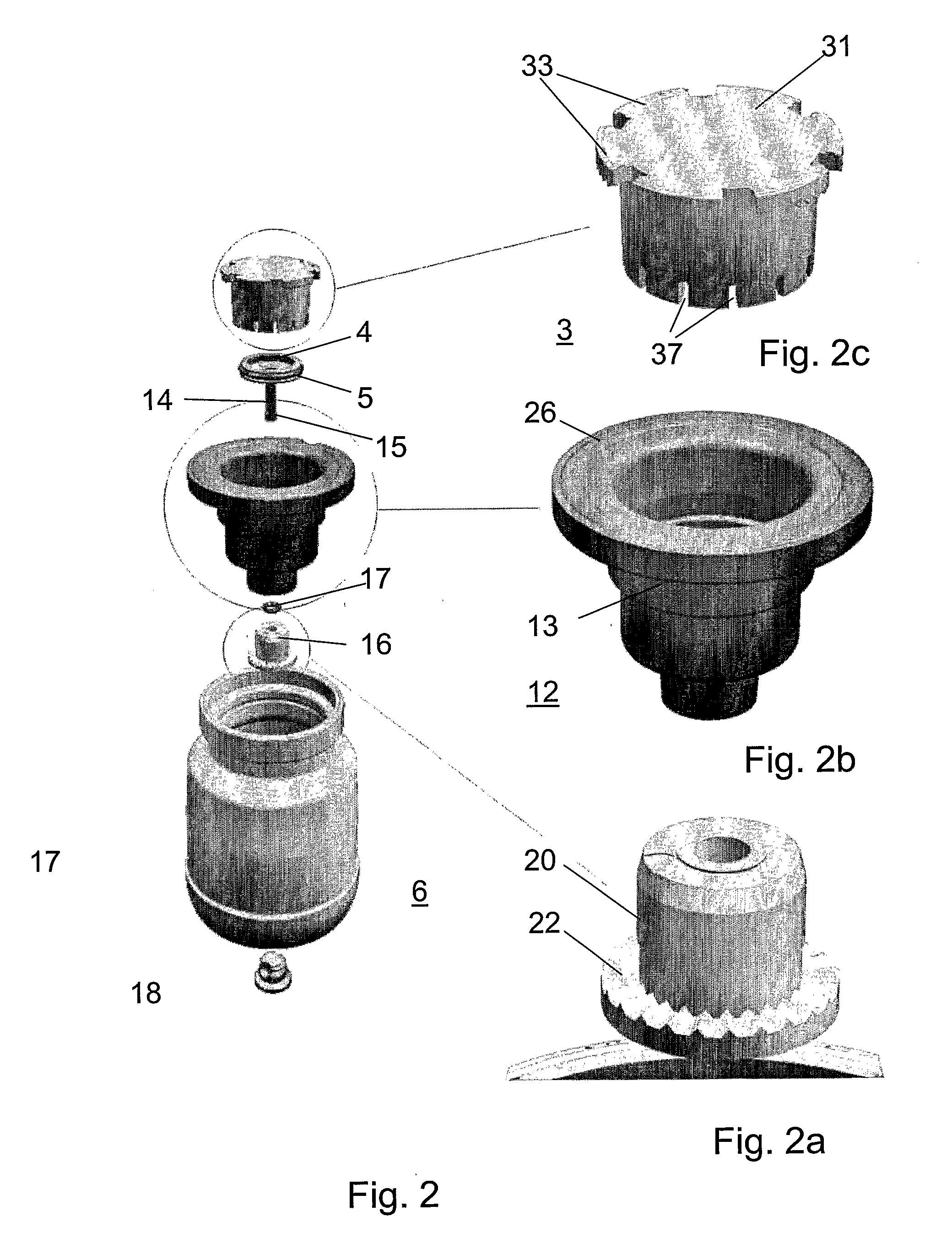
[0018]In FIGS. 1 and 2a pressure control device 1 for maintaining a constant predetermined excess pressure in a container is shown in perspective and in exploded view. The device 1 comprises a first chamber 2 provided by a first cylinder or cup-like insert 3 with a movable piston 4 with a large O-ring 5 and a second chamber 6 provided by a bottle-type second cylinder 7 with an open end 8 and a closed end 9. The open end 8 of the cylinder 7 has a tapered neck part 10 and a flange 11, on which a ring-shaped insert or closure 12 with a stepped funnel 13 is mounted, in which the cup-like insert 3 is fixed. The piston 4 has a stem 14 with an end part 15 of larger diameter (FIG. 2). A stop element 16 with an sealing O-ring 17 are mounted at the other end of the closure 12, which provides together with a valve seat in the closure a clo...


PUM

PropertyMeasurementUnit
angleaaaaaaaaaa
pressureaaaaaaaaaa
lengthaaaaaaaaaa

Abstract

A novel pressure control device is provided comprising a first cylinder (3) at a predetermined excess pressure, a piston (4) with a sealing ring (5) being movable within said first cylinder, and a second cylinder (7). The first cylinder (3) is encompassed by the second cylinder (7) as to form a ring-shaped passage which is leading to the outside. A valve in said passageway is released and closed by a stem (14) of the piston (4). The open end of the first cylinder (3) is provided with at least one axially directed incision (37), such that the piston (4) with the sealing ring (5) introduced in the first cylinder (3) and covering the end of the incision (37) is in a non-pressurized position. The stem (14) has a stop element (15) which closes the valve in the upper position of the piston, wherein the piston stroke essentially defines the excess pressure.

Description

CROSS REFERENCE TO RELATED APPLICATIONS[0001]This application is entitled to the benefit of and incorporates by reference essential subject matter disclosed in International Patent Application No. PCT / IB2005 / 052571 filed on Aug. 1, 2005.FIELD OF THE INVENTION[0002]The present invention concerns a pressure control device for a fluid dispensing container for maintaining a constant predetermined excess pressure and a method for manufacturing such a pressure control device.BACKGROUND OF THE INVENTION[0003]Containers with pressure control devices are known in patent literature since almost thirty years but until today no commercial products are available on the market.[0004]In EP-A-0 349 053 a pressure capsule for a spray can is described, which consists of two chambers. The first chamber is filled with a fluid under relatively high pressure and the second chamber is filled with a fluid with a pressure equal to the overpressure which normally exists in the spray can and needed for expell...

Claims


Application Information

Patent Timeline
Patent Type & Authority Applications(United States)
IPC IPC(8): F16K27/02B21D51/16
CPCY10T29/49405B65D83/663
Inventor REGAN, PHILVAN SWIETEN, ROYVAN WIERINGEN, NIELS
Owner I P S RES & DEV
Why Eureka
Try Eureka