
Transformer and manufacturing method of transformer

a transformer and manufacturing method technology, applied in the field of transformers, can solve the problems of affecting the transformation efficiency of the transformer, insufficient winding space for the coil, etc., and achieve the effects of reducing the thickness of the bobbin assembly, high power density, and easy understanding and implementation

Pending Publication Date: 2021-03-04
LITE ON ELECTRONICS (GUANGZHOU) LTD +1
View PDF18 Cites 0 Cited by
  • Summary
  • Abstract
  • Description
  • Claims
  • Application Information

AI Technical Summary

Benefits of technology

The transformer described in this patent has a hollow bobbin with no blocking plates, which reduces the thickness of the bobbin assembly. This makes it conform to the trend of thinning products and also allows for higher power density. The manufacturing method is easy to implement.

Problems solved by technology

In a case where the distance between the upper blocking plate and the lower blocking plate decreases with the reducing thickness of the bobbin, although the development trend of thinning of products is conformed to, sufficient winding space cannot be provided for the coil, and even the transformation efficiency of the transformer is affected.

Method used


Image

  • Transformer and manufacturing method of transformer
  • Transformer and manufacturing method of transformer
  • Transformer and manufacturing method of transformer

Examples


Embodiment Construction

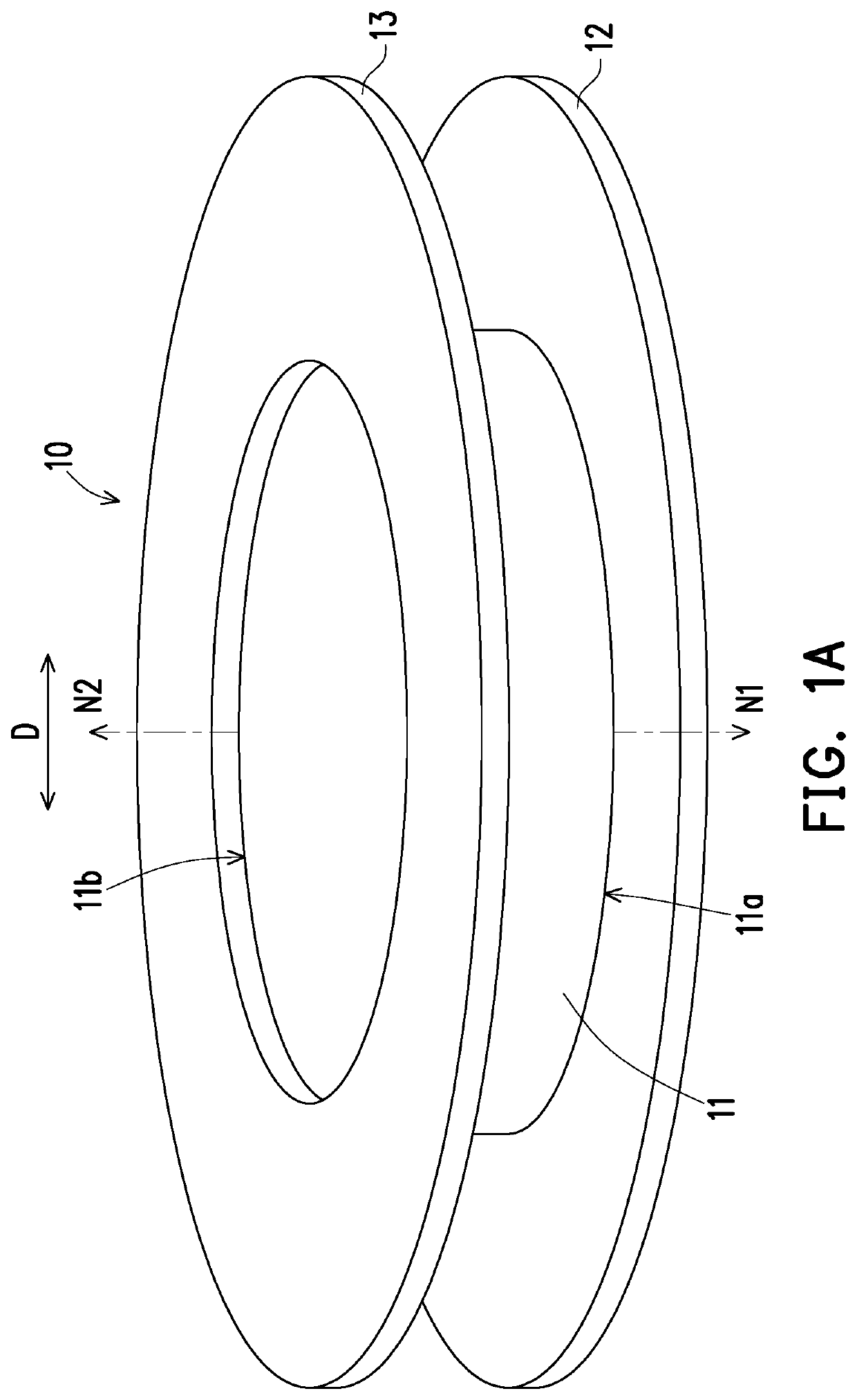
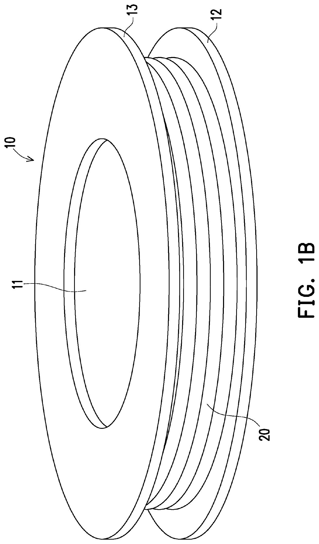
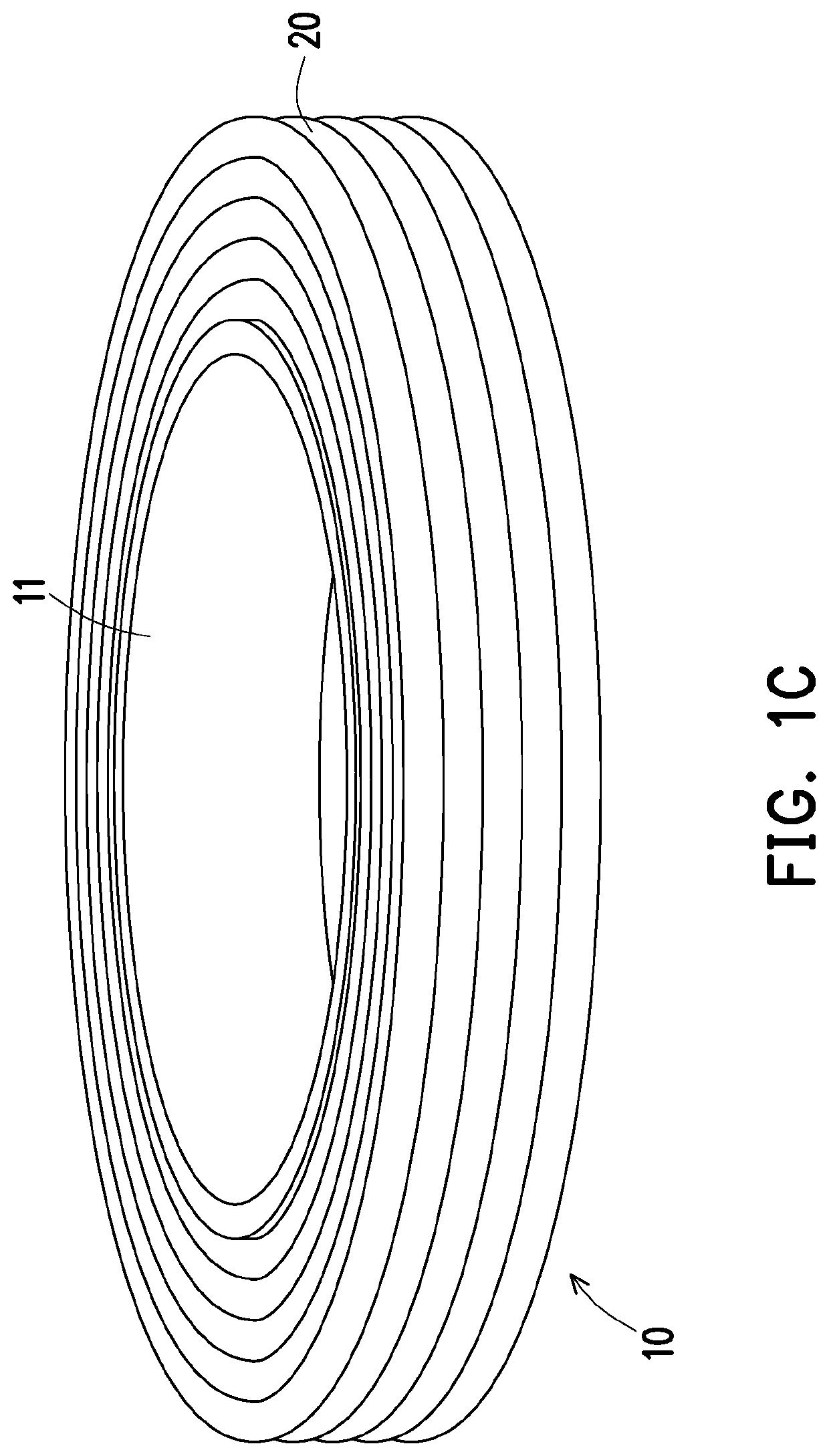
[0030]FIG. 1A to FIG. 1C are schematic views showing a manufacturing process of a bobbin assembly in a transformer according to an embodiment of the disclosure. Firstly, referring to FIG. 1A, a hollow bobbin 11 is provided. The hollow bobbin 11 is a hollow cylinder, but is not limited thereto. In other embodiments, the hollow bobbin is a hollow square cylinder or other hollow polygonal cylinders. Specifically, the bobbin 11 includes a first end surface 11a and a second end surface 11b opposite to each other, and in a direction D perpendicular to a normal N1 of the first end surface 11a and a normal N2 of the second end surface 11b, a first blocking plate 12 extends outward from the first end surface 11a and the second blocking plate 13 extends outward from the second end surface 11b. More specifically, the first blocking plate 12 is detachably mounted to the first end surface 11a, and the second blocking plate 13 is detachably mounted to the second end surface 11b.

[0031]In one of t...


PUM

PropertyMeasurementUnit
magneticaaaaaaaaaa
thicknessaaaaaaaaaa
power densityaaaaaaaaaa

Abstract

A transformer includes a hollow bobbin, a coil and a magnetic core. The hollow bobbin has a first end surface and a second end surface opposite to each other. In a direction perpendicular to the normals of the first end surface and the second end surface of the hollow bobbin, the hollow bobbin is not configured with any blocking plates extending laterally from the first end surface and the second end surface. The coil is wound on the hollow bobbin to form a bobbin assembly. The magnetic core has an accommodating space, wherein the bobbin assembly is disposed in the accommodating space. A manufacturing method of the transformer is also provided.

Description

CROSS-REFERENCE TO RELATED APPLICATION[0001]This application claims the priority benefit of China application serial no. 201910794232.1, filed on Aug. 27, 2019. The entirety of the above-mentioned patent application is hereby incorporated by reference herein and made a part of this specification.BACKGROUND1. Technical Field[0002]The disclosure relates to a power supply product, particularly to a transformer and a manufacturing method of the transformer.2. Description of Related Art[0003]In order to conform to the development trend of thinning of power supply products, the overall size of the transformer is gradually reduced, and especially, it is the most common practice to reduce the thickness of a bobbin in a transformer. Generally speaking, the bobbin is mostly provided with an upper blocking plate and a lower blocking plate. The upper blocking plate extends from a side edge of an upper end of the bobbin, and the lower blocking plate extends from a side edge of a lower end of the...

Claims


Application Information

Patent Timeline
Patent Type & Authority Applications(United States)
IPC IPC(8): H01F27/32H01F27/24H01F41/061
CPCH01F27/325H01F41/061H01F27/24H01F27/306H01F41/06H01F41/00H01F41/098
Inventor CHEN, CHIH-SHAN
Owner LITE ON ELECTRONICS (GUANGZHOU) LTD
Learn More