
Steerable drive wheel

a steering wheel and drive wheel technology, applied in the direction of propulsion parts, transportation and packaging, electric propulsion mounting, etc., can solve the problems of complex mecanum wheels, high cost, and inability to carry heavy loads, and achieves high maneuverability, low weight, and easy to track straight

Pending Publication Date: 2021-03-04
CONCEPTUAL INNOVATIONS
View PDF10 Cites 5 Cited by
  • Summary
  • Abstract
  • Description
  • Claims
  • Application Information

AI Technical Summary

Benefits of technology

This patent describes a new type of steerable drive wheel for carts and wheeled objects. It is low-cost, lightweight, powerful, and easy to maneuver. It can track straight lines with ease and is adaptable to different applications. This new design solves most of the problems of previous steerable drive wheels.

Problems solved by technology

Mecanum wheels are complex, require many component parts, are typically heavy and characteristically are plagued with traction shortcomings.
They also do not have good load carry capabilities and are susceptible to damage by debris on the ground.
Although high on traction, tank drives have significant maneuverability limitations.
Swerve drives are very popular but have certain drawbacks which include: high mass (heavy), design complexity and they require two different motors (one for drive and another for steerage).

Method used


Image

  • Steerable drive wheel
  • Steerable drive wheel
  • Steerable drive wheel

Examples


Embodiment Construction

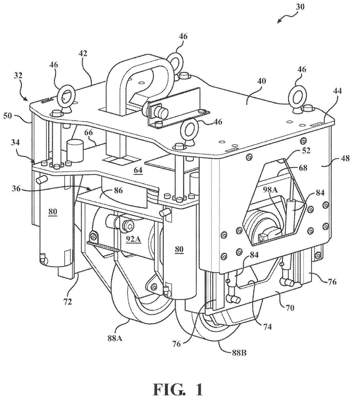
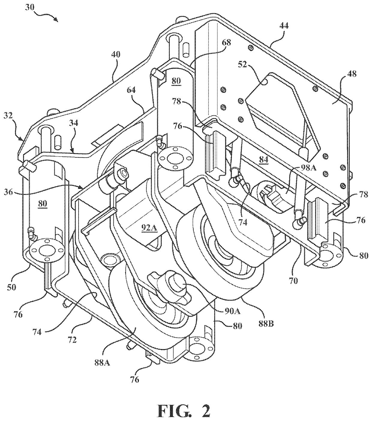
[0033]Referring to the figures, wherein like numerals indicate like or corresponding parts throughout the several views, a steerable drive wheel assembly according to a first exemplary embodiment of the invention is generally shown at 30 in FIGS. 1-17. Generally stated, the drive wheel assembly 30 is composed of three interacting sub-assemblies or components: an outer housing 32, an intermediate suspension module 34 and a drive module 36. Each component will be described in turn.

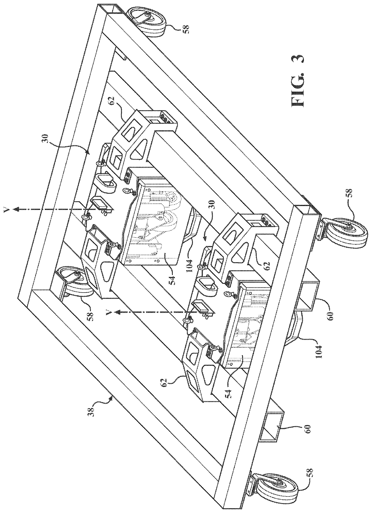
[0034]The outer housing 32 is both a structural member for the assembly 30 as well as an exterior shell within which is defined an interior space used to shelter, at least partially, the intermediate suspension module 34 and drive module 36 components. The structural attributes of the outer housing 32 arise from the fact that the assembly 30 attaches to a cart or other wheeled object through the outer housing 32. For example, FIGS. 3-6 depict two steerable drive wheel assemblies 30 joined to a lift cart 38 v...


PUM


Abstract

A steerable drive wheel assembly includes two independently motor-driven wheels. The wheels are supported in side-by-side orientation for independent rotation about a common horizontal rolling axis, and equally laterally offset from said vertical steering axis. The wheels and their respective drive motors are carried in a drive module that is mounted like a turret under an intermediate suspension module via a rotary bearing. The intermediate suspension module is mounted on linear bearing assemblies within an outer housing. Biasing members urge the intermediate suspension module together with its drive module downwardly to maintain traction with a floor. A compact configuration is achieved by overlapping the drive motors with the opposite wheels. Position control is achieved by a strategic sensor array. Electrical wire management is achieved by a serpentine energy chain located in the plane of the rotary bearing.

Description

CROSS REFERENCE TO RELATED APPLICATIONS[0001]This application claims priority to Provisional Patent Application US 62 / 893,423 filed on Aug. 29, 2019, the entire disclosure of which is hereby incorporated by reference and relied upon.BACKGROUND OF THE INVENTION[0002]Field of the Invention. The invention relates generally to motorized carts and the like of the type used in various settings, including but not limited to industrial material handling and educational robotics, and more particularly to steerable motorized drive unit therefor.[0003]Description of Related Art. Steerable motorized carts of all sorts are commonly used in factories and other industrial settings to transport heavy industrial materials from one location to another. In another common application, lightweight nimble steerable motorized carts are used in radio-controlled settings for educational, recreational and competitive purposes. These are merely offered as examples; steerable motorized carts may be found in ma...

Claims


Application Information

Patent Timeline
Patent Type & Authority Applications(United States)
IPC IPC(8): B62D7/14B62D7/22
CPCB62D7/142B60K1/02B62D7/22B62D7/023B60Y2200/62B60K7/0007B60K2007/0038B60K2007/0061B60K17/30B66F9/063B66F9/07586
Inventor LEE, ELMERBRETES, TYLERAERTS, MICHAEL ANTHONYLOTSBAICH, RYAN JOSEPH
Owner CONCEPTUAL INNOVATIONS
Learn More