Method and mould for manufacturing preforms for a wind turbine rotor blade

a technology for wind turbines and rotor blades, which is applied in the field of manufacturing methods and moulds for manufacturing preforms for wind turbine rotor blades, can solve the problems of large manufacturing space, time-consuming and expensive manufacturing of preforms of different shapes and sizes, and the inability to manufacture molds for preforms, so as to improve the layup process and ensure the effect of safety

Pending Publication Date: 2021-03-04
LM WIND POWER INT TECH II APS
View PDF6 Cites 4 Cited by
  • Summary
  • Abstract
  • Description
  • Claims
  • Application Information

AI Technical Summary

Benefits of technology

The present invention is related to a method for manufacturing wind turbine blade preforms using a flexible and cost-efficient process. The inventors found that combining a plurality of support elements and strips made of steel or composite material can allow for the production of various shapes and sizes of preform molds in a simple and cost-effective way. The strips are arranged on the support elements in a side-by-side fashion and can be positioned either edge-to-edge or with a certain gap between them. The support elements and strips can be hingedly interconnected, which provides flexibility and variability when arranging the strips. The preform molds have a flat molding surface that can cover the entire circumference of the blade half, which improves the layup process and prevents the formation of wrinkles in the shell structure.

Problems solved by technology

This usually requires large space for manufacturing and for storing the preforms.
In addition, the manufacturing of preforms of different shapes and sizes can be time-consuming and expensive.
In particular, the manufacturing of moulds for preforms can be tedious and costly, which applies all the more if preforms of various shapes and curvatures are required.

Method used


Image

  • Method and mould for manufacturing preforms for a wind turbine rotor blade
  • Method and mould for manufacturing preforms for a wind turbine rotor blade
  • Method and mould for manufacturing preforms for a wind turbine rotor blade

Examples


Embodiment Construction

[0071]The invention is explained in detail below with reference to embodiments shown in the drawings, in which

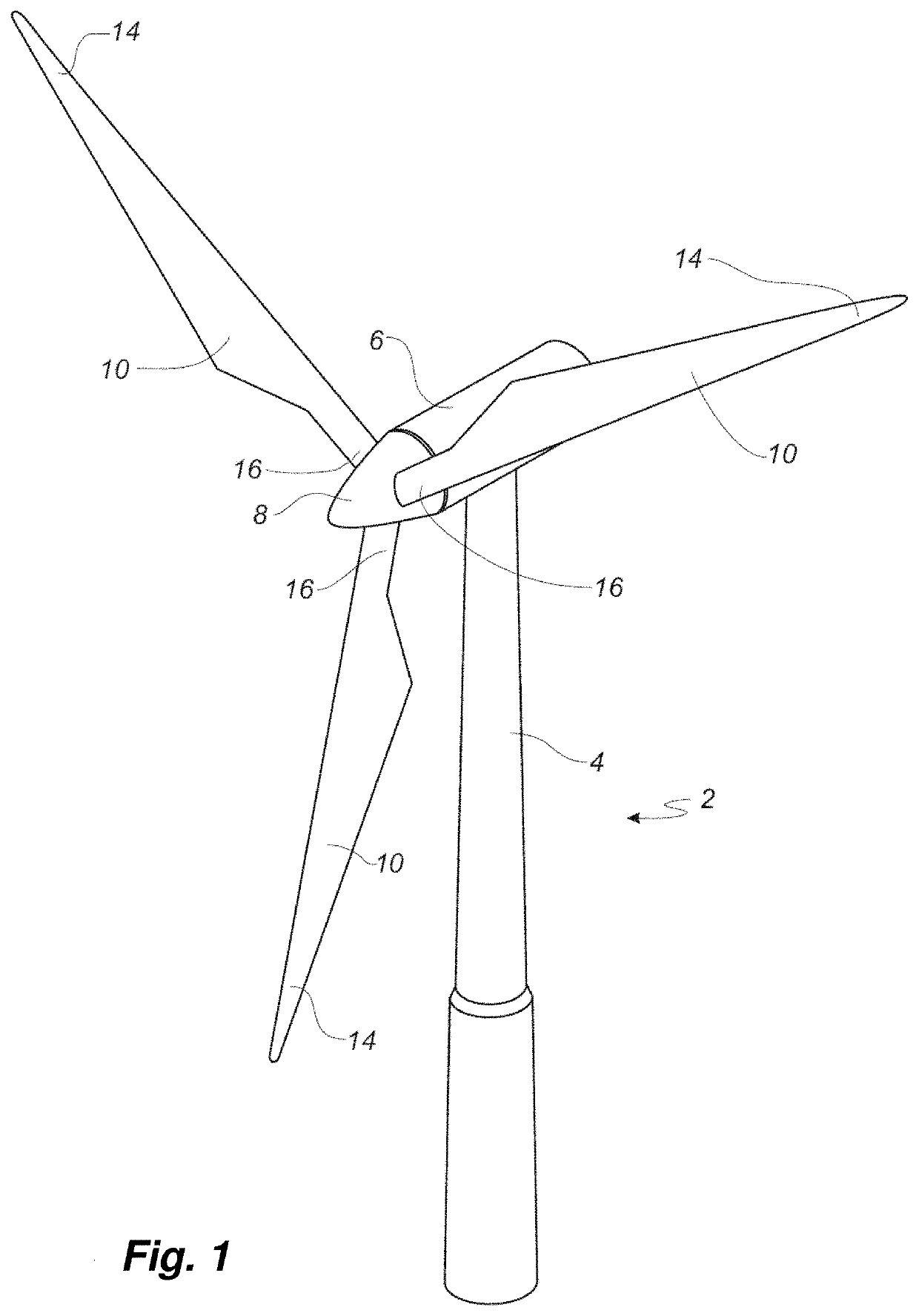
[0072]FIG. 1 shows a wind turbine,

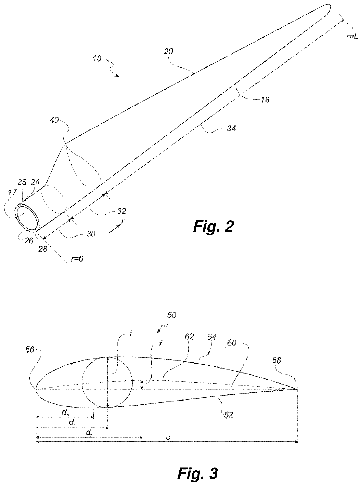
[0073]FIG. 2 shows a schematic view of a wind turbine blade,

[0074]FIG. 3 shows a schematic view of an airfoil profile through section I-I of FIG. 4,

[0075]FIG. 4 shows a schematic view of the wind turbine blade, seen from above and from the side,

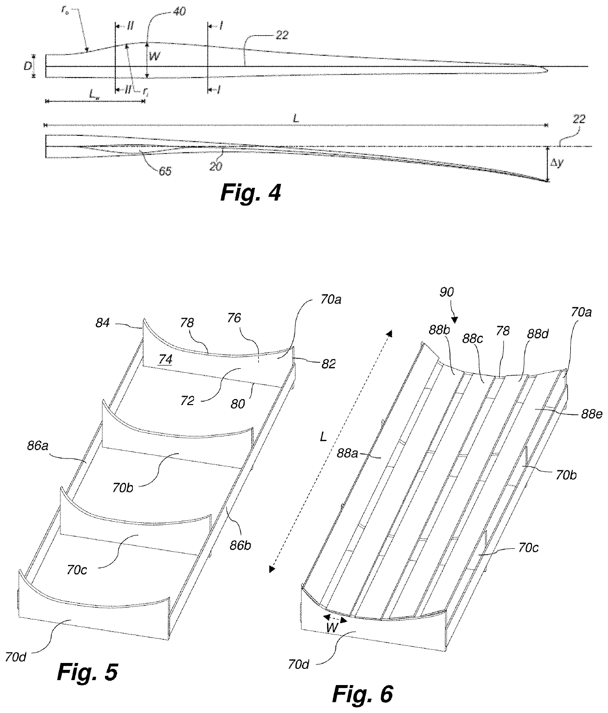
[0076]FIG. 5 is a perspective drawing of an arrangement of support elements for a preform mould according to the present invention,

[0077]FIG. 6 is a perspective drawing of a preform mould according to the present invention,

[0078]FIG. 7 is a perspective drawing of another embodiment of a preform mould according to the present invention,

[0079]FIG. 8 is a perspective drawing illustrating an arrangement of support elements for a preform mould according to another embodiment of the present invention,

[0080]FIG. 9 is a perspective drawing of a support element according to an embodiment of the present inventi...


PUM

PropertyMeasurementUnit
lengthaaaaaaaaaa
lengthaaaaaaaaaa
widthaaaaaaaaaa

Abstract

The present invention relates to a method of manufacturing a preform for a wind turbine blade and to a preform mould. The method involves providing a plurality of support elements (70), each support element (70) comprising a planar member (72), arranging a plurality of strips (88) on the top surface (78) of the planar member (72) of each support element (70), wherein the strips (88) are arranged in juxtaposition. Subsequently, a fibre material and a binding agent may be laid on at least part of the strips (88) for forming the preform.

Description

FIELD OF THE INVENTION[0001]The present invention relates to a method of manufacturing a preform for a wind turbine blade, to a preform mould for manufacturing a preform for a wind turbine blade and to a method of manufacturing a wind turbine blade part.BACKGROUND OF THE INVENTION[0002]The rotor blades of modern wind turbines capture kinetic wind energy by using sophisticated blade design created to maximise efficiency. There is an increasing demand for large wind blades which may exceed 80 metres in length and 4 metres in width. The blades are typically made from a fibre-reinforced polymer material and comprise a pressure side shell half and a suction side shell half, also called blade halves. The cross-sectional profile of a typical blade includes an airfoil for creating an air flow leading to a pressure difference between both sides. The resulting lift force generates torque for producing electricity.[0003]The shell halves of wind turbine blades are usually manufactured using bla...

Claims


Application Information

Patent Timeline
Patent Type & Authority Applications(United States)
IPC IPC(8): B29C70/84B29C70/48B29B11/16B29C33/30
CPCB29C70/84B29C70/48B29L2031/085B29C33/307B29B11/16B29D99/0028B29C70/30Y02P70/50Y02E10/72
Inventor LEHMANN MADSEN, KRISTIAN
Owner LM WIND POWER INT TECH II APS
Why Eureka
Try Eureka