Localization of a surveying instrument

Active Publication Date: 2021-02-18
LEICA GEOSYSTEMS AG
View PDF2 Cites 4 Cited by
  • Summary
  • Abstract
  • Description
  • Claims
  • Application Information

AI Technical Summary

Benefits of technology

This patent aims to provide an automated and robust localization method that can be used for various surveying instruments. The method should provide the necessary accuracy and minimize user interaction. Additionally, the method should allow for matching algorithm to be run even when only a small subset of the site has been seen. This is important to minimize any drift of the SLAM system and improve matching accuracy. The method utilizes a deformable CAD layout model which can improve matching when the SLAM system drifts. The differences between the CAD model and the SLAM point cloud can improve the robustness of SLAM and quality assurance for the architect or BIM information management system.

Problems solved by technology

Such a real world coordinate system can often deviate from the planed one, be it as a result of tolerances, mistakes, aging, etc. or simply as the environment itself changes, e.g. as dimensions of a building changed due to adaptions or application of new cladding or insulation, by attachments of additional constructions, by unplanned items or vegetation at the site, etc.

Method used


Image

  • Localization of a surveying instrument
  • Localization of a surveying instrument
  • Localization of a surveying instrument

Examples


Embodiment Construction

[0051]The diagrams of the figures should not be considered as being drawn to scale. Where appropriate, the same reference signs are used for the same features or for features with similar functionalities. Different indices to reference signs are used to differentiate between different embodiments of a feature which are exemplarily shown. The term “substantially” is used to express that a feature can, but in general is not required to be realized exactly up to 100%, but only in such a way that a similar or equal technical effect can be achieved. In particular slight deviation, due to technology, manufacturing, constructional considerations, etc. can occur, while still within the meaning of the scope.

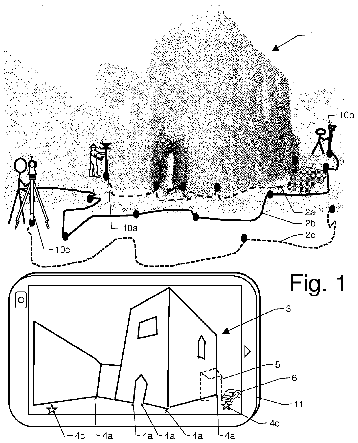
[0052]FIG. 1 schematically shows a possible example of an embodiment of an application of a method for localization of a movable surveying instrument with respect to its environment according to the invention.

[0053]A Localization of the surveying instrument to a local or global coordinate...


PUM


Abstract

A method for surveying an environment by a movable surveying instrument configured to be carried by a human with a progressional capturing of 2D-images by at least one camera and applying a visual simultaneous location and mapping algorithm (VSLAM) or a visual inertial simultaneous location and mapping algorithm (VISLAM) with a progressional deriving of a sparse evolving point cloud of at least part of the environment, and a progressional deriving of a trajectory of movement. The method comprises a progressional matching of the sparse evolving point cloud with a known CAD-geometry, with a minimizing of a function configured to model a distance between the sparse point cloud and the known CAD-geometry and deriving a spatial localization and orientation of the surveying instrument. At least one surveying measurement value of the environment by a spatial measurement unit is combined with the sparse point cloud or the plan information.

Description

CROSS-REFERENCE TO RELATED APPLICATIONS[0001]This application claims priority to European Patent Application No. 19191324.3, filed on Aug. 12, 2019. The foregoing patent application is herein incorporated by reference.FIELD OF INVENTION[0002]The invention relates to a method for localization of a movable surveying instrument, which can also at least partially be embodied as a stored computer program product, and to a corresponding movable surveying instrument according.BACKGROUND[0003]In the technical field of surveying, in particular with a construction work or geodetic accuracy, it is often not only demanded to establish exact measurements of the environment by the instrument, but also to derive a localization of the instrument in its environment. Therein, in particular in view of automated BIM (building information modeling) Systems and Databases, the demands on correctness and in particular on unambiguousness is increasing, wherefore e.g. a basic localization by defining a site,...

Claims


Application Information

Patent Timeline
IPC IPC(8): G06T7/70G06T7/60G06T7/30G01C11/02
CPCG06T7/70G01C11/02G06T7/30G06T7/60G01C15/002G01C11/025G01C11/06G01S17/89G01S5/16
Inventor TÖRÖK, ZOLTÁNMÖRWALD, THOMAS
Owner LEICA GEOSYSTEMS AG
Why Eureka
Try Eureka