
Cyclone cooler device

a cooling device and cyclone technology, applied in the field of cooling devices, can solve the problems of reducing thermal capacity, not having the same ability to cool transient applications such as pulsed power electronic systems, and not having the same ability to cool transient applications

Active Publication Date: 2021-02-18
GENERAL ELECTRIC CO
View PDF0 Cites 0 Cited by
  • Summary
  • Abstract
  • Description
  • Claims
  • Application Information

AI Technical Summary

Benefits of technology

The patent describes a device called a cold plate assembly that helps to cool down a heat source. It is made up of an outer housing and one or more fluid passages that have a special design to create a swirling flow of cooling fluid. This helps to remove the heat from the heat source and keep it cool. Overall, the cold plate assembly helps to efficiently cool down the heat source and improve its performance.

Problems solved by technology

While the cooling of some known steady-state power conversion applications has improved from various packaging and other cooling improvements, these improvements have not been shown to have the same ability to cool transient applications such as pulsed power electronic systems.
For example, some known cooling applications that integrate cooling devices into the packaging of the electronic systems have been found to have decreased thermal capacity associated with increasing package integration.

Method used


Image

  • Cyclone cooler device
  • Cyclone cooler device
  • Cyclone cooler device

Examples


Embodiment Construction

[0021]Embodiments of the subject matter described herein provide cooling devices, packages, and methods that provide higher thermal capacitances while maintaining lower thermal resistances to cooling fluids than at least some known cooling devices, packages, and methods. While the Background describes cooling issues with respect to transient applications (e.g., pulsed electronics), one or more (or each) of the embodiments described herein may be used to cool steady-state and / or transient applications.

[0022]At least one embodiment of the cooler device described herein is referred to as a package integrated cyclone cooler (PICCO) device. The cooler device provides increased thermal capacity using a two-phase re-condensing cyclone cooler, which has superior heat transfer and critical heat flux performance than other cooling devices.

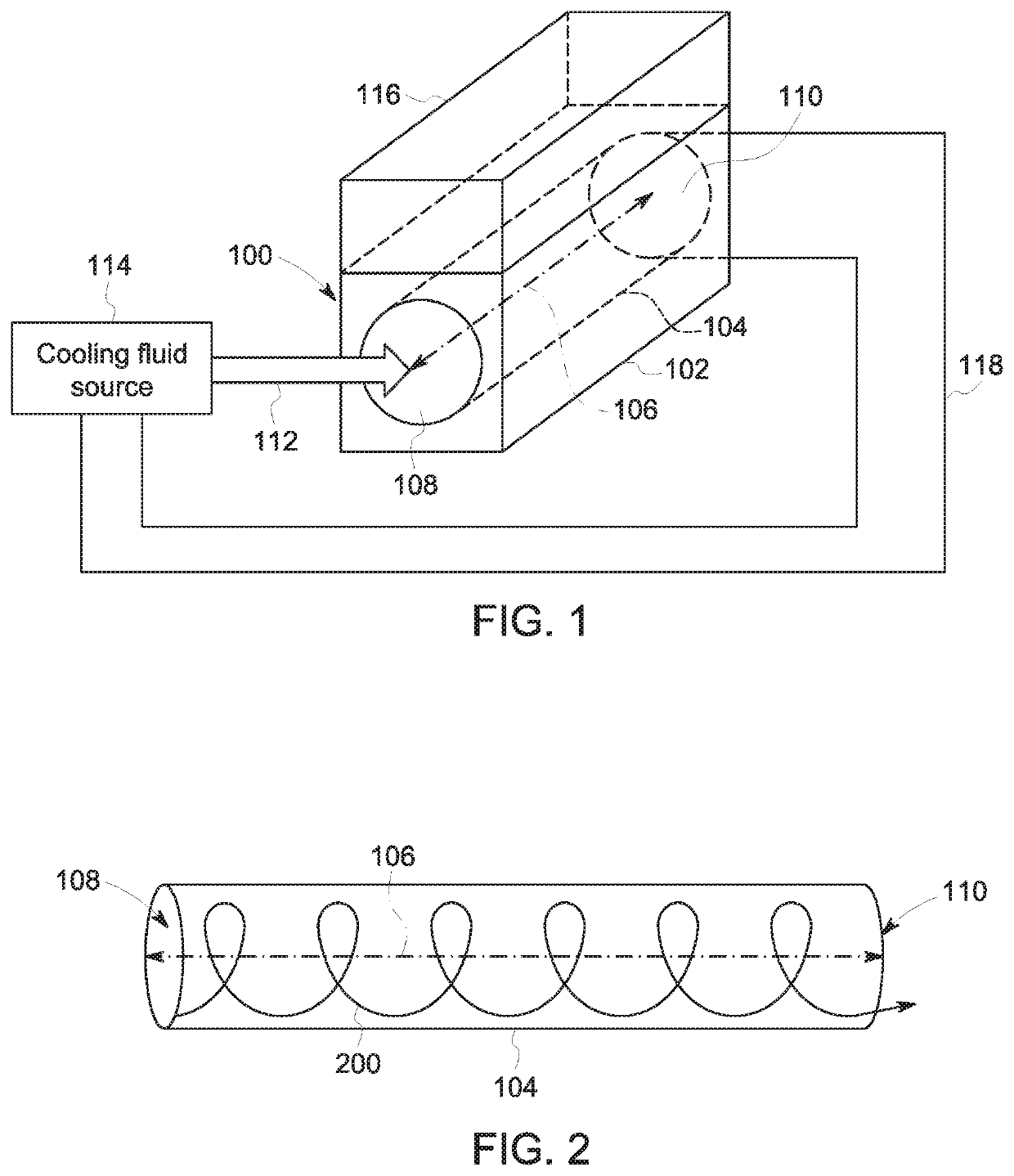
[0023]FIG. 1 schematically illustrates a perspective view of one embodiment of a cooler device 100. The cooler device 100 optionally can be referred to as a...


PUM


Abstract

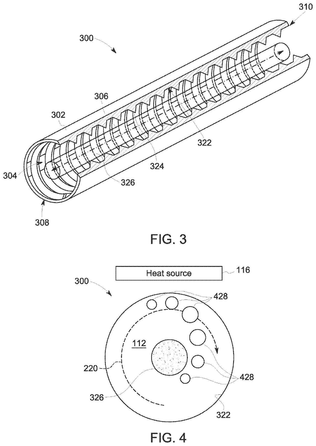
A cyclone cooler device includes a housing that defines an interior channel elongated along a center axis. One or more of the fluid passage or configuration of an inlet end of the channel is shaped to induce a swirling flow of a cooling fluid within the channel while the channel is thermally coupled with one or more heat sources. The swirling flow of the cooling fluid removes thermal energy from and cools the one or more heat sources. During the swirling flow, the cooling fluid rotates around the center axis of the channel while also moving along the length of the center axis. The cooling fluid changes phases during the swirling flow to cool the heat source(s).

Description

FIELD[0001]The subject matter described herein relates to cooling devices.BACKGROUND[0002]The growth in use of pulsed power electronic systems has demonstrated a corresponding increasing need for improved cooling applications to remove heat from these electronic systems. While the cooling of some known steady-state power conversion applications has improved from various packaging and other cooling improvements, these improvements have not been shown to have the same ability to cool transient applications such as pulsed power electronic systems. For example, some known cooling applications that integrate cooling devices into the packaging of the electronic systems have been found to have decreased thermal capacity associated with increasing package integration. This creates a potential for increased peak junction temperatures and temperature swings during transient operation of the electronic systems when pulse widths approach a thermal time constant of the packaging of the electroni...

Claims


Application Information

Patent Timeline
Patent Type & Authority Applications(United States)
IPC IPC(8): F28D15/02F28F13/12
CPCF28D15/0233F28D2021/0028F28F13/12F28D1/0246F28F1/022F28F7/02F28F1/40H01L23/467H05K7/20254
Inventor DE BOCK, HENDRIK PIETER JACOBUSBOURASSA, COREYGERSTLER, WILLIAM DWIGHT
Owner GENERAL ELECTRIC CO
Learn More