
Gas generating compositions

Active Publication Date: 2021-02-18
SAUDI ARABIAN OIL CO
View PDF0 Cites 0 Cited by
  • Summary
  • Abstract
  • Description
  • Claims
  • Application Information

AI Technical Summary

Benefits of technology

The patent text discusses the drawbacks of using conventional wellbore fluids, such as sudden changes in formation type and strength leading to fracture gradients and loss of circulation. Additionally, the text highlights the issue of residual drilling fluid left behind casing in a completed well, which can cause collapse from sustained casing pressure or annular pressure buildup. The text also emphasizes the poor compressibility of set cement to sustain cyclic stresses, poor cement-to-casing bond, and the formation of microannuli when using conventional cementing fluids. These issues can reduce well productivity and increase well maintenance costs. Therefore, the patent aims to address these problems to improve wellbore fluid performance.

Problems solved by technology

Because of this, when conventional fluid is used for drilling, sudden changes in formation type and formation strength may lead to “kicks” (unexpected formation fluid influxes to the well), collapse of the bore by pressured formation fluids, and loss of circulation of the drilling fluid into a particularly weak formation.
Drilling fluid left behind a casing may also lead to sustained casing pressure (SCP) or annular pressure build up (APB) due to thermal expansion of residual drilling fluid left behind casing, making the casing susceptible to collapse.

Method used


Image

  • Gas generating compositions
  • Gas generating compositions
  • Gas generating compositions

Examples


example 1

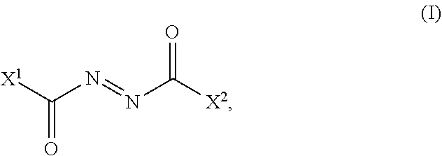
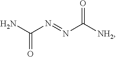
[0254]1.5 g of azodicarbonamide solid were added to 50 milliliters of 0.8% xanthan solution and stirred vigorously for an hour to obtain a well-dispersed stable suspension. 10 ml (containing 0.3 g of azodicarbonamide) of the suspension was added to several graduated cylinders. Then, foaming surfactants and amine activators were added, as specified in Table 1. The suspension was stirred and the cylinders were kept in a water bath heated to 140° F. The initial fluid volume before measurements was 12 ml. The gas volumes were measured periodically. The results are shown in Table 1.

TABLE 1A1B2C3D4pHE5F6G7H8Foam stabilityNone0.4Carbohydrazide 0.3 g7.0505879160Slightlyheterogeneousbubble sizes0.150.4Carbohydrazide 0.3 g—555879160Stable,homogeneousbubbles0.15NoneCarbohydrazide 0.3 g—582862 32Unstable foamNone0.4Toluene sulfonyl 0.5 g6.81212 0 0No foamsemicarbazide0.150.4Toluene sulfonyl 0.5 g—1212 0 0semicarbazide0.150.4 mlToluene sulfonyl0.45 g—324473107hydrazide0.150.4TEPA0.15 ml—334070 9...

example 2

[0255]The results for diutan solutions are shown in Table 2. In a typical procedure, 0.5% by volume of diutan solution in water was employed. Azodicarbonamide was added with vigorous stirring, which was continued until all the solid was uniformly dispersed and suspended. In a typical experiment, 0.5 g azodicarbonamide was suspended in 10 ml of diutan solution, followed by addition of foaming surfactant (sodium lauryl sulfate, 0.4 ml), and the activator. The gas measurements were made at room temperature. The starting volume of the fluid in each experiment was 12 ml.

TABLE 2A1B2C3D4E5F6G7DETA0.5 mln.d.,20  40 ml / 26 hrs40   56 (in 26 hrs)Carbohydrazide0.5 g1717>80 ml29>136 (in 48 hrs)NaOH (solid)0.5 g2025>80 ml52>136 (in 48 hrs)1activator2activator amount3fluid volume in 60 min, ml.4fluid volume is 100 min, ml.5final volume after 48 hours, ml (estimated)6% gas in 100 min7gas amount ml / g of azo compound at room temperature

[0256]The results of Examples 1 and 2 show that (1) organic amine...


PUM

PropertyMeasurementUnit
Temperatureaaaaaaaaaa
Volumeaaaaaaaaaa
Volumeaaaaaaaaaa

Abstract

The present application provides a gas-generating aqueous fluid containing a gas-generating compound like an azo compound, and an organic amine like a primary, secondary or tertiary amine, a hydrazine, a hydrazide, or a semicarbazide. The aqueous fluid may also a viscosifler, and a foaming surfactant. The present application also provides a method of using the gas-generating composition to modulate density of a wellbore fluid for use in downhole applications. The method optionally includes adding an oxidizer to the wellbore fluid.

Description

CLAIM OF PRIORITY[0001]This application is a divisional of and claims the benefit of U.S. application Ser. No. 16 / 282,245 filed on Feb. 21, 2019. The entire contents of the previous application is incorporated herein by reference.TECHNICAL FIELD[0002]This disclosure relates to aqueous fluids containing a gas-generating compound that may be used in wellbore applications.BACKGROUND[0003]Recoverable fluids, such as hydrocarbons (for example, petroleum, natural gas, combinations of them) and water, are frequently found in subterranean formations. Production of a recoverable fluid from a subterranean formation often requires drilling onto the subterranean formation to produce a wellbore through which the recoverable fluid is brought to the surface. Wellbore fluids such as drilling fluids, carrier fluids, fracturing fluids, spotting fluids, cementing fluids, completion fluids, stimulation fluids, remedial fluids and clean-up fluids are used in the wellbore to perform multiple functions, s...

Claims


Application Information

Patent Timeline
IPC IPC(8): C09K8/035C09K8/42C09K8/60C09K8/62
CPCC09K8/035C09K8/62C09K8/60C09K8/42C09K8/38C09K8/473C04B40/0039C04B38/02C09K8/703C09K8/94C04B22/068C04B24/121C04B24/129C04B2103/40C04B2103/44C04B24/122C04B24/16C04B24/38C04B24/123C04B24/383C04B28/02
Inventor REDDY, B. RAGHAVA
Owner SAUDI ARABIAN OIL CO
Learn More