
Optical detection system, blood cell analyzer, and platelet detection method

a detection system and platelet technology, applied in the field of biological inspection technology, can solve the problems of amplitude changes, frequency shifts, power peaks, and inability to differentiate pulse signals generated by normal plt from those generated by interfering small pulses, and achieve the effect of improving the detection precision of blood cell analyzers

Active Publication Date: 2021-02-11
SHENZHEN MINDRAY BIO MEDICAL ELECTRONICS CO LTD
View PDF0 Cites 3 Cited by
  • Summary
  • Abstract
  • Description
  • Claims
  • Application Information

AI Technical Summary

Benefits of technology

The present patent provides an optical detection system, a blood cell analyzer, and a platelet detection method. This system effectively isolates reflected light generated when laser beams are propagated in an optical path, resulting in a stable output of laser beams. This improves the detection efficiency of blood cell samples and reduces interference caused by small pulses, resulting in improved detection precision of the blood cell analyzer.

Problems solved by technology

The optical detection system in a blood cell analyzer generally uses a laser as a light source, and the laser is susceptible to reflected light in an optical path and becomes unstable, resulting in amplitude changes, frequency shifts, and / or power peaks, etc.
However, to deeply analyze the small signal characteristics of the optical pulses to obtain more clinical information, for example, when analyzing platelet (PLT) particles in an optical channel, these interfering small pulses are confused with small pulses generated by normal PLT particles, resulting in the inability to differentiate pulse signals generated by normal PLT from that generated by the interfering small pulses.

Method used


Image

  • Optical detection system, blood cell analyzer, and platelet detection method
  • Optical detection system, blood cell analyzer, and platelet detection method
  • Optical detection system, blood cell analyzer, and platelet detection method

Examples


Embodiment Construction

[0052]The present disclosure will be further described below in detail in combination with the accompanying drawings and the embodiments. It should be understood that the embodiments provided herein are only for explaining the present disclosure, but not for limiting the present disclosure. In addition, the embodiments provided below are a part of embodiments for implementing the present disclosure, but not all embodiments. And in a non-conflict case, the technical solutions recorded in the embodiments of the present disclosure can be implemented in an arbitrary combination way.

[0053]It should be noted that, in the embodiments of the present disclosure, the term ‘include’, ‘comprise’, or any other variant is intended to cover a non-exclusive meaning, such that a method or a device comprising a series of elements not only comprises expressly recorded elements but also comprises other elements not expressly listed, or further comprises inherent elements for implementing the method or ...


PUM

PropertyMeasurementUnit
reflectivityaaaaaaaaaa
light collection angleaaaaaaaaaa
wavelengthaaaaaaaaaa

Abstract

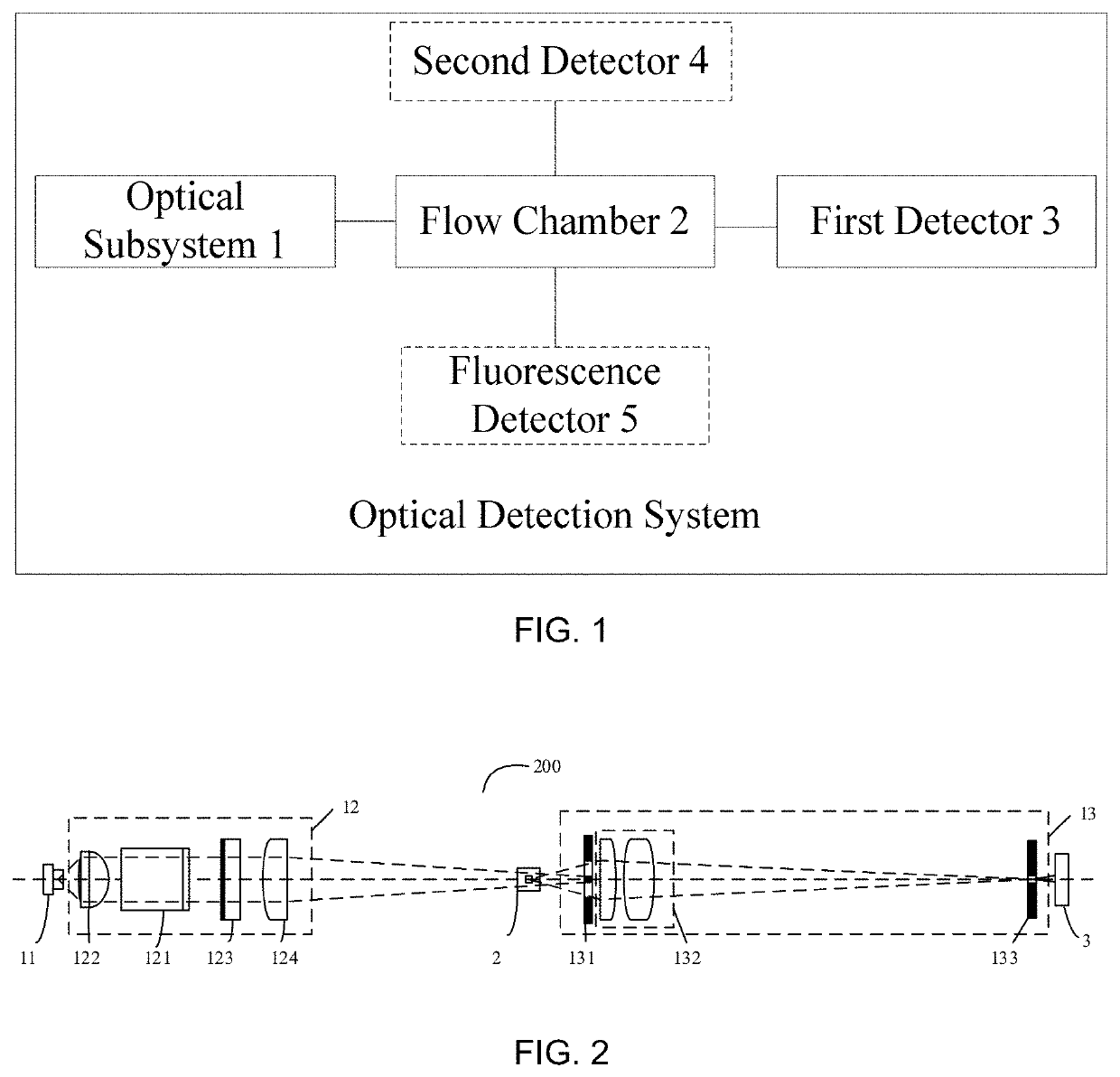
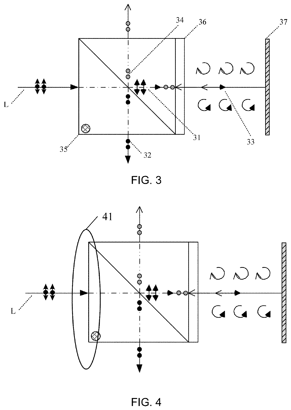
An optical detection system, a blood cell analyzer and a platelet detection method are provided. The optical detection system includes: an optical subsystem, a flow chamber and a first detector; the optical subsystem includes a laser, a front optical assembly including an optical isolator, and a rear optical assembly including a blocking diaphragm. The laser is configured to emit a laser beam; the front optical assembly is configured to perform front optical treatment; the rear optical assembly is disposed downstream of the flow chamber in the propagation direction of the laser beam, and is configured to perform rear optical treatment on the scattered light and the laser beam converged at the blocking diaphragm; and the optical isolator is configured to isolate reflected light that is generated when the laser beam passes through the flow chamber.

Description

CROSS-REFERENCE[0001]This application is a continuation of International Application No. PCT / CN2019 / 084509, filed Apr. 26, 2019, which claims priority benefit of Chinese Patent Application No. 201810405048.9, filed Apr. 28, 2018, the contents of which are incorporated herein by reference.TECHNICAL FIELD[0002]The disclosure relates to biological inspection technology and, in particular, to an optical detection system, a blood cell analyzer, and a platelet detection method.BACKGROUND ART[0003]The optical detection system in a blood cell analyzer generally uses a laser as a light source, and the laser is susceptible to reflected light in an optical path and becomes unstable, resulting in amplitude changes, frequency shifts, and / or power peaks, etc.[0004]In practical applications, when power peaks are generated due to unstable oscillation of the laser, they appear in optical forward signals as small pulses, and the amplitudes of these small pulses are much smaller than that of effective...

Claims


Application Information

Patent Timeline
Patent Type & Authority Applications(United States)
IPC IPC(8): G01N21/64G01N21/47
CPCG01N21/6486G01N33/487G01N21/47G01N2015/1006G01N15/1434G01N15/1459G01N2015/018
Inventor YI, QIUSHIWANG, DONGSHENGDAI, YONG
Owner SHENZHEN MINDRAY BIO MEDICAL ELECTRONICS CO LTD
Learn More