Common carrier network device, network system, and program
- Summary
- Abstract
- Description
- Claims
- Application Information
AI Technical Summary
Benefits of technology
Problems solved by technology
Method used
Image

Examples
embodiment 1
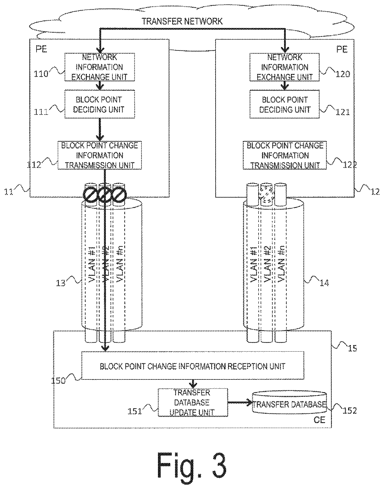
[0046]FIG. 3 is a diagram illustrating a network system 301 that connects a plurality of PEs and a single CE to realize redundancy between the PE and the CE. In a case where the change of the block point is that “block point is newly set”, the block point change information notification unit of the PE in the network system 301 performs notification of the change of the block point by using a transmission path including the logical port for which the block point is newly set.
[0047]The network system 301 includes two PEs (11, 12) and one CE 15, a transmission path 13 connecting the PE 11 and the CE 15, and a transmission path 14 connecting the PE 12 and the CE 15. The PE 11 includes a network information exchange unit 110, a block point deciding unit 111, and a block point change information transmission unit 112. The PE 12 includes a network information exchange unit 120, a block point deciding unit 121, and a block point change information transmission unit 122. The CE 15 includes a...
embodiment 2
[0058]FIG. 5 is a diagram illustrating a network system 302 that connects a plurality of PEs and a single CE to realize redundancy between the PE and the CE. In a case where the change of the block point is that “block point is released.” the block point change information notification unit of the PE in the network system 302 performs notification of the change of the block point by using a transmission path including the logical port for whiCh the block point is released.
[0059]The network system 302 includes two PEs (21, 22) and one CE 25, a transmission path 23 connecting the PE 21 the CE 25, and a transmission path 24 connecting the PE 22 and the CE 25. The PE 21 includes a network information exchange unit 210, a block point deciding unit 211, a block point change information transmission unit 212, and a transfer database 213. The PE 22 includes a network information exchange unit 220, a block point deciding unit 221, a block point change information transmission unit 222, and a...
embodiment 3
[0065]FIG. 6 is a diagram illustrating a network system 303 that connects a plurality of PEs and a plurality of CEs to realize redundancy between the PE and the CE.
[0066]The network system 303 includes two PEs 31, 32 and two CEs 35, 36, a transmission path 33 connecting the PE 31 and the CE 35, a transmission path 34 connecting the PE 32 and the CE 36, and a transmission path 37 connecting the CEs 35 and 36. The PE 31 includes a network information exchange unit 310, a block point deciding unit 311, a block point change determination unit 312, a block point setting information transmission unit 313, a block point release information transmission unit 314, and a transfer database 315. The PE 32 includes a network information exchange unit 320, a block point deciding unit 321, a block point change determination unit 322, a block point setting information transmission unit 323, a block point release information transmission unit 324, and a transfer database 325. The CE 35 includes a bl...
PUM
 Abstract
Description
Claims
Application Information
 - R&D
- Intellectual Property
- Life Sciences
- Materials
- Tech Scout
- Unparalleled Data Quality
- Higher Quality Content
- 60% Fewer Hallucinations
Browse by: Latest US Patents, China's latest patents, Technical Efficacy Thesaurus, Application Domain, Technology Topic, Popular Technical Reports.
© 2025 PatSnap. All rights reserved.Legal|Privacy policy|Modern Slavery Act Transparency Statement|Sitemap|About US| Contact US: help@patsnap.com