Circuit breaker

A circuit breaker and device body technology, applied in the field of circuit breakers, can solve the problems of cumbersome work of assembling parts, a large number of parts, complex structure, etc., and achieve the effects of easy installation work, shortened disconnection time, and simplified structure

Inactive Publication Date: 2005-09-21
MATSUSHITA ELECTRIC WORKS LTD
View PDF1 Cites 0 Cited by
  • Summary
  • Abstract
  • Description
  • Claims
  • Application Information

AI Technical Summary

Problems solved by technology

[0003] In the existing example, the structure of the circuit breaker is: there are connecting rods, working plates and cross bars between the handle and the movable contact, and the movable contacts are driven by the working plate and the cross bar. Therefore, there are Due to the large number of parts and complex structure, the work of assembling parts to the body is cumbersome.

Method used


Image

  • Circuit breaker
  • Circuit breaker
  • Circuit breaker

Examples


Embodiment Construction

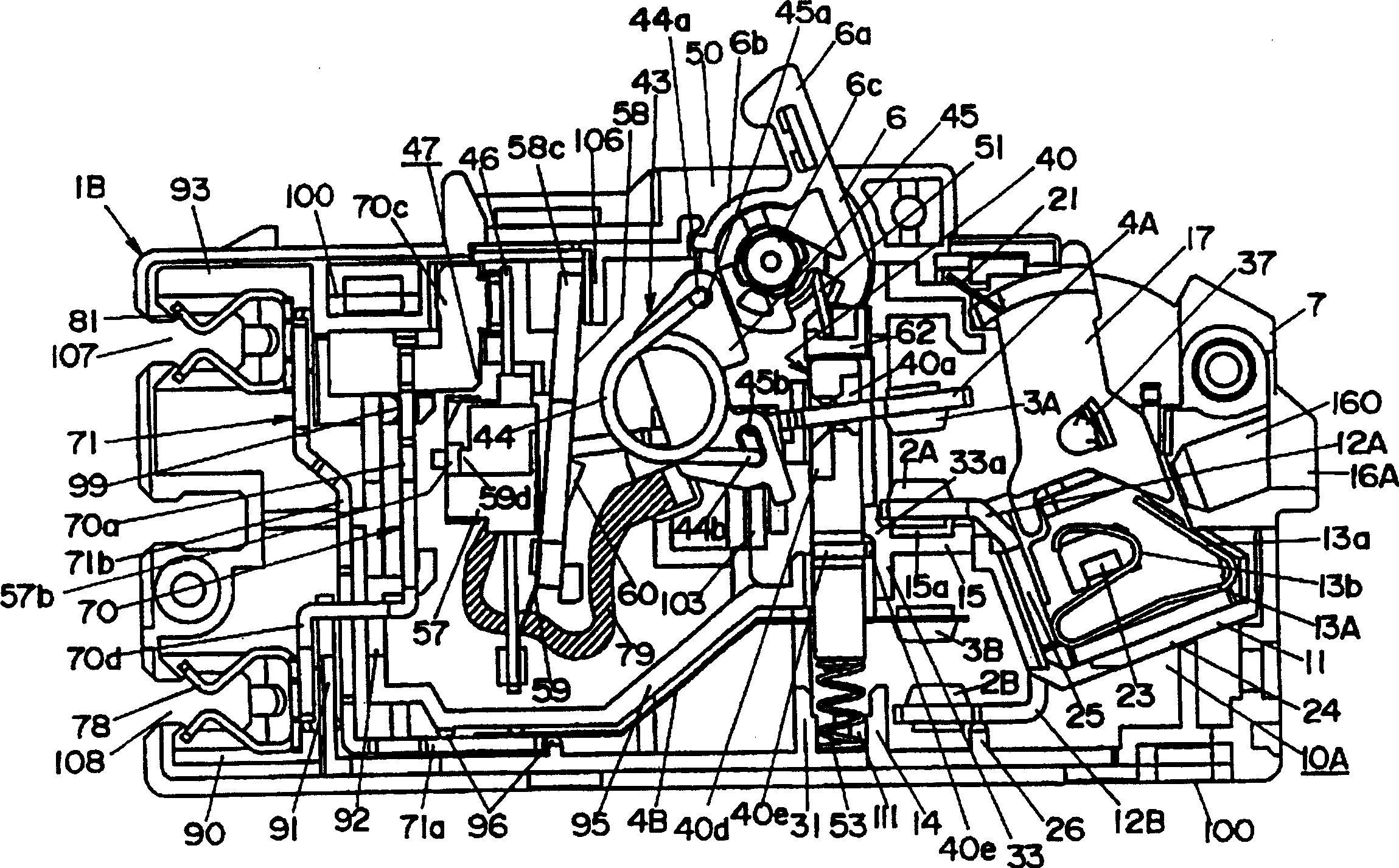
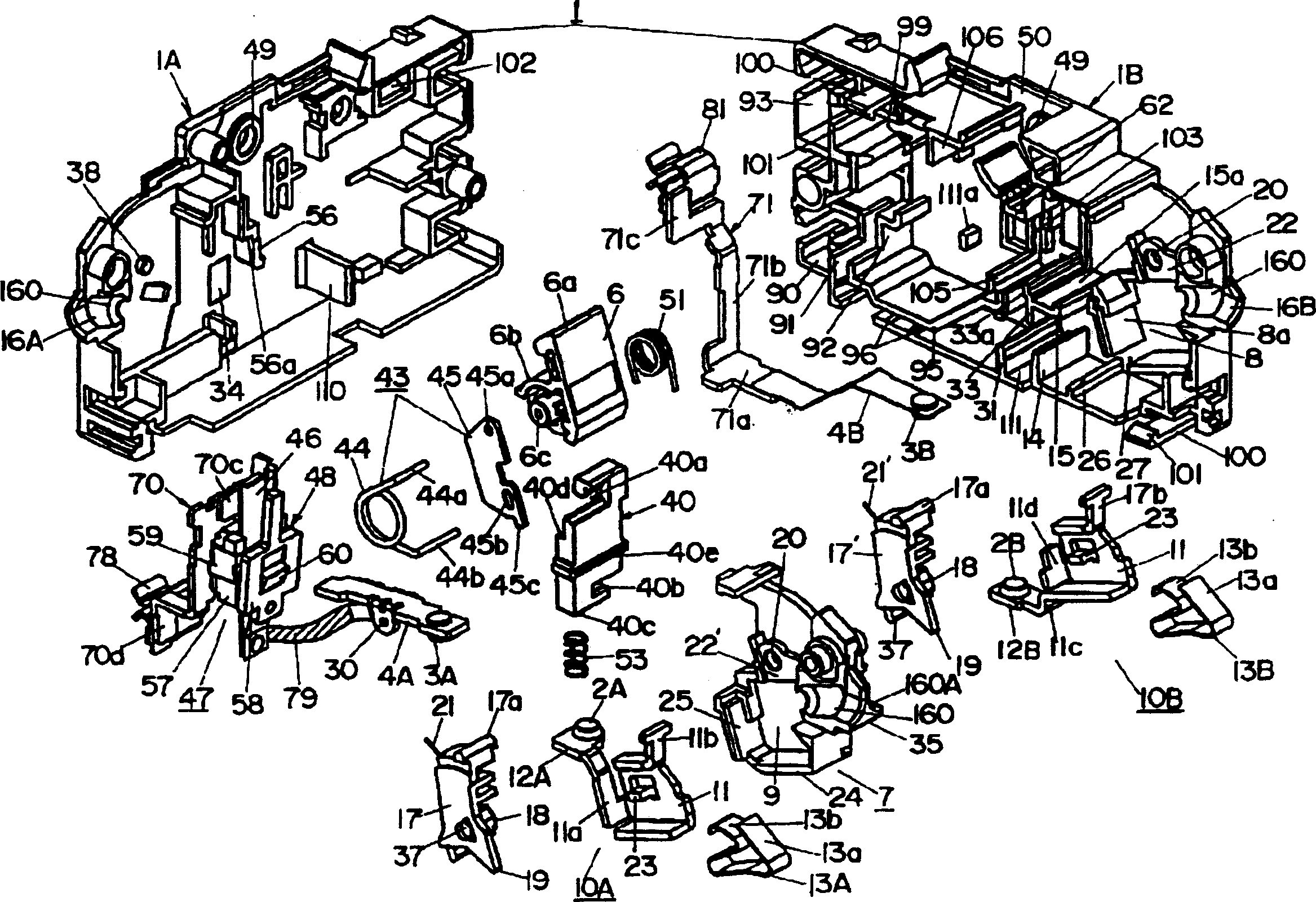
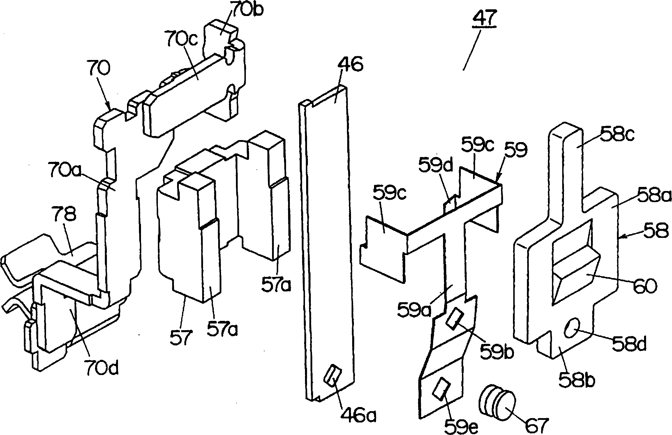
[0049] Below, refer to Figure 1 to Figure 11 An embodiment of the present invention will be described.

[0050] The circuit breaker of the present embodiment includes: in the body 1 formed by connecting the first side case 1A and the second side case 1B made of synthetic resin on both sides, two side by side in the width direction of the body 1 Fixed contacts 2A, 2B; two movable contacts 4A, 4B of movable contacts 3A, 3B that are opposite to each fixed contact 2A, 2B and can be freely contacted and separated; drive these two movable contacts 4A, 4B of the opening and closing mechanism 5; and, according to the closing and opening operation of the handle 6, each movable contact 3A, 3B is connected (contacted, separated) with each fixed contact 2A, 2B through the opening and closing mechanism 5; In the height direction of the body 1, each fixed contact 2A, 2B and each movable contact 4A, 4B are arranged up and down, and among the two movable contacts 4A, 4B, there are two fixed...


PUM


Abstract

A breaker. An open-close mechanism 5 to open and close movable contacts 4A, 4B is composed of a handle 6, a coupling member 43 to couple the handle 6 with a movable contact 4A of voltage electrode side, a latch member 58 having a protruding latch part 60 to lock (latch) the rear end part of the movable contact 4A, and a driving member 40 or the like. The coupling member 43 is only interposed between the handle 6 and the movable contact 4A, and because the movable contact 4A is made to be directly latched to a latch member 58, therefore the structure can be simplified compared with that of a conventional one, and the work to incorporate parts to the instrument body 1 becomes easier.

Description

technical field [0001] The invention relates to a circuit breaker. Background technique [0002] A conventional circuit breaker is disclosed in JP-A-2001-15007. In the conventional circuit breaker described in the publication, the operating plate is connected to the handle through a connecting rod. When the handle is turned with one end side of the operating plate stopped by the stop member, the other end of the operating plate will The cross bar pressed by the side rotates, and the movable contact supported together with the compression spring that provides contact pressure to the cross bar rotates together with the cross bar to close the contact part. [0003] In the existing example, the structure of the circuit breaker is: there are connecting rods, working plates and cross bars between the handle and the movable contact, and the movable contacts are driven by the working plate and the cross bar. Therefore, there are Due to the large number of parts and complex structu...

Claims


Application Information

Patent Timeline
Patent Type & Authority Patents(China)
IPC IPC(8): H01H71/12H01H73/00H01H73/36H01H73/50
Inventor 水野初男田中孝信冈田健彦泽田知行稻次崇
Owner MATSUSHITA ELECTRIC WORKS LTD
Why Eureka
Try Eureka