Optical fiber sensing

Pending Publication Date: 2021-02-04
UNIV OF SOUTHAMPTON
View PDF0 Cites 2 Cited by
  • Summary
  • Abstract
  • Description
  • Claims
  • Application Information

AI Technical Summary

Benefits of technology

The patent text describes a way to increase the amount of radiation reflected back from an optical fiber by adding reflectors along its length. These reflectors serve to increase the signal to noise ratio of the reflected radiation, making it easier to measure. The reflectors act as preconfigured reflection sites, which can help improve the quality of the reflected signal. By doing this, the need for expensive and complex optical amplification stages in the sensor system can be avoided. The patent also mentions that the reflectors can cause some transmission loss in the fiber, which may limit the range of measurements. To address this, the refractive index difference between the reflectors and adjacent regions of the fiber can be minimized to decrease transmission loss. Overall, the patent proposes a simple and cost-effective way to improve the sensing capabilities of optical fibers by increasing the amount of reflected radiation.

Problems solved by technology

The relatively small magnitude of the Rayleigh scattering signal can also impose limitations on a distance range over which measurements can be made and / or a spatial resolution of the measurements.

Method used


Image

  • Optical fiber sensing
  • Optical fiber sensing
  • Optical fiber sensing

Examples


Embodiment Construction

[0104]Before particular examples of the present invention are described, it is to be understood that the present disclosure is not limited to the particular embodiments described herein. It is also to be understood that the terminology used herein is used for describing particular examples only and is not intended to limit the scope of the claims.

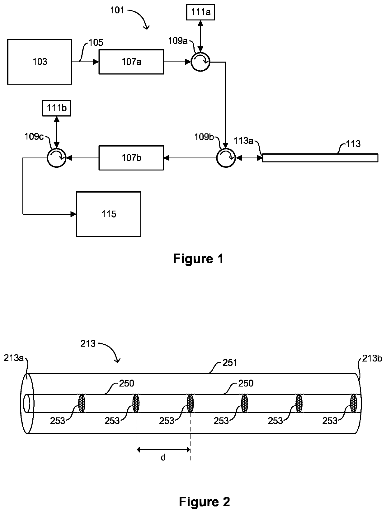
[0105]FIG. 2 is a schematic depiction of an optical fiber 213 according to embodiments of the invention. The optical fiber 213 is suitable for use in a sensing system. For example, the optical fiber 213 may be used in a sensing system of the type described above with reference to FIG. 1, where the optical fiber 113 described above is replaced with an optical fiber 213 of the type depicted in FIG. 2.

[0106]The optical fiber 213 comprises a core 250 surrounded by a cladding 251. The optical fiber 213 includes a first end 213a at which radiation may be received so as to couple the radiation into the fiber 213 and a second end 213b remote from t...


PUM


Abstract

A sensor system includes a radiation source, an optical fiber, and a detection device. The radiation source is arranged to emit pulses of radiation. The optical fiber comprises a first end and a core. The first end is arranged to receive pulses of radiation output from the radiation source such that, in use, the pulses of radiation are coupled into the fiber. The core is arranged to support propagation of the pulses of radiation along the fiber. The core includes a plurality of reflectors each comprising a portion of the core having a refractive index which is different to the refractive index of adjacent regions of the core. Reflections of a pulse of radiation from adjacent reflectors output at the first end of the fiber are resolvable from each other in the time domain. The detection device is arranged to measure radiation output from the first end of the fiber and resolve radiation reflected at different locations in the core of the fiber.

Description

CROSS-REFERENCES TO RELATED APPLICATIONS[0001]This application claims priority to and is a continuation of International Patent Application No. PCT / GB2019 / 050460, filed Feb. 20, 2019; which claims priority to GB Patent Application No. 1802708.6, filed Feb. 20, 2018, the entire contents of which are hereby incorporated by reference in their entirety for all purposes.TECHNICAL FIELD[0002]The present disclosure relates to apparatus and methods for sensing using an optical fiber. Aspects of the invention relate to a sensor system, a detection device, an optical fiber, a method of manufacture of an optical fiber and a sensing method.BACKGROUND OF THE INVENTION[0003]The use of optical fibers for sensing has found numerous applications in a variety of fields including construction, oil and gas, transportation, manufacturing and security. Typically, radiation is coupled into an optical fiber and transmission and / or reflection of the radiation from the fiber is measured in order to derive me...

Claims


Application Information

Patent Timeline
IPC IPC(8): G01D5/353G01H9/00
CPCG01D5/35367G01D5/35361G01D5/35329G01D5/35325G01H9/004G01D5/3538G01D5/35354
Inventor DONKO, ANDREIMASOUDI, ALIBERESNA, MARTYNASBRAMBILLA, GILBERTO
Owner UNIV OF SOUTHAMPTON
Why Eureka
Try Eureka