
Thumb Brace

a technology of thumb brace and thumb, which is applied in the field of thumb brace/orthosis, can solve the problems of preventing or preventing the movement of fingers, preventing or inhibiting the posture of hand and finger that a patient is still able, and preventing or inhibiting the natural palm posture associated with the hand and finger

Inactive Publication Date: 2021-01-21
WE DESIGN BEHEER BV
View PDF4 Cites 2 Cited by
  • Summary
  • Abstract
  • Description
  • Claims
  • Application Information

AI Technical Summary

Benefits of technology

This invention is about a hand device that allows patients to pinch their thumb and index finger naturally while maintaining a round / oval shape. The device has a palm engaging portion that supports the palm and helps to distribute its pressure. This allows for a more comfortable and effective grip while pinching. The device is designed with a concave palm engaging portion that mimics a natural posture and shape of the hand. The device is made entirely of wire, which maintains a sleek design and allows for air circulation and hygiene. Overall, this invention improves the ability of patients to pinch their thumb and index finger with comfort and ease.

Problems solved by technology

However, the known wire based thumb braces primarily focus on resolving issues of the thumb only but in doing so may unnecessarily impede or discourage particular movements of the fingers and / or postures of the hand and finger that a patient is still able to tolerate.
For example, known wire-based thumb braces may discourage or impede natural palm posture associated when pinches fingers.

Method used


Image

  • Thumb Brace
  • Thumb Brace
  • Thumb Brace

Examples


embodiment 1

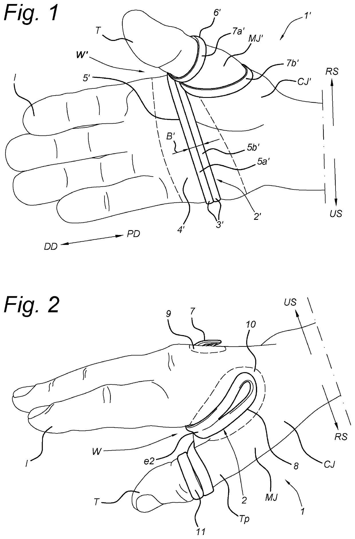
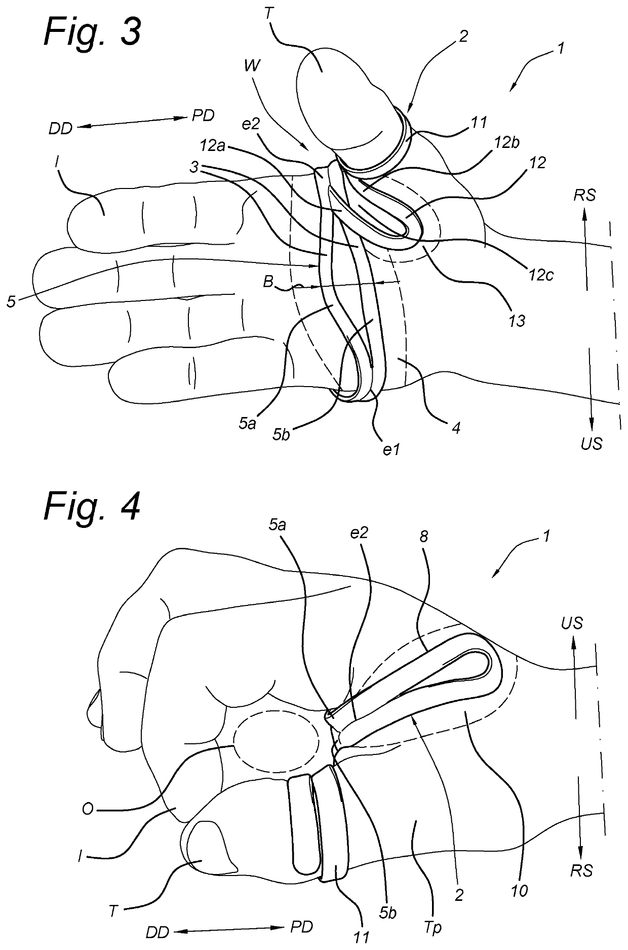
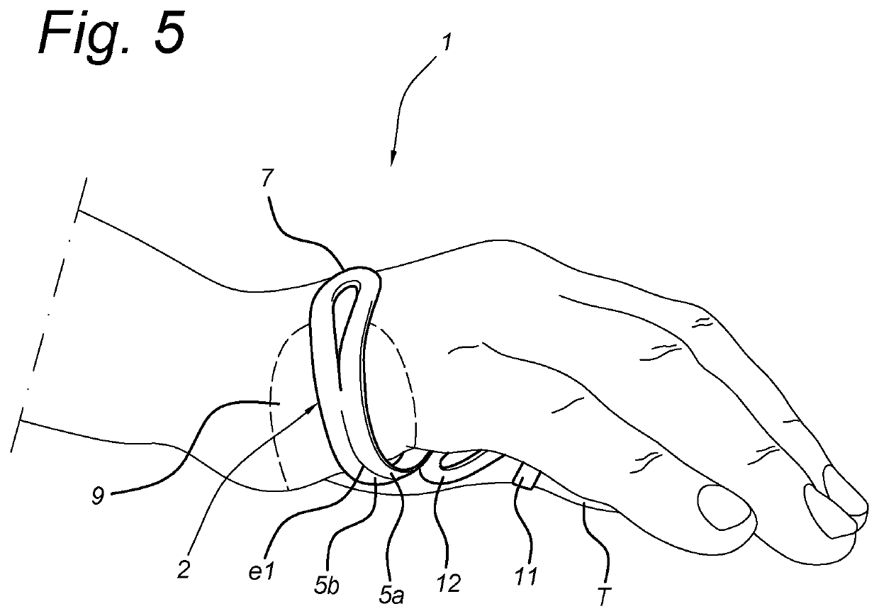
[0044]A thumb brace (1) for support of a thumb (T), comprising a wire frame (2) having

[0045]a palmar wire section (3) configured to extend in lateral direction from a web point (W) thereof between a thumb (T) and index finger (I) along a palmar region (4) of the hand toward an ulnar side of the hand, wherein the palmar wire section (3) is connected to

[0046]an ulnar wire section (7) and a radial wire section (8), the ulnar wire section (7) being configured to extend from the ulnar side of the hand in lateral direction along a dorsal ulnar region (9) of the hand and wherein the radial wire section (8) is configured to extend from the web point (W) along a first dorsal interosseous region (10), wherein the wire frame (2) further comprises

[0047]a ring shaped thumb wire section (11) configured to receive the thumb (T), and wherein the palmar wire section (3) comprises a palm engaging portion (5) that widens in proximal-distal direction.

embodiment 2

[0048]The thumb brace (1) according to embodiment 1, wherein the palm engaging portion (5) comprises two wire parts (5a, 5b) connected parallel at an ulnar side end (e1) and opposing radial side end (e2) of the palmar wire section (3), and wherein the two wire parts (5a, 5b) are separated in proximal-distal direction between the ulnar and radial side ends (e1, e2).

embodiment 3

[0049]The thumb brace (1) according to embodiment 1 or 2, wherein the palm engaging portion (5) is a concave palm engaging portion.


PUM


Abstract

A thumb brace (1) comprising a wire frame (2) having a palmar wire section (3) configured to extend in lateral direction from a web point (W) thereof between a thumb (T) and index finger (I) along a palmar region (4) toward an ulnar side of the hand. The palmar wire section (3) is connected to an ulnar wire section (7) and radial wire section (8), the ulnar wire section (7) being configured to extend from the ulnar side along a dorsal ulnar region (9) of the hand and wherein the radial wire section (8) is configured to extend from the web point (W) along a first dorsal interosseous region (10) of the hand. The wire frame (2) further comprises a ring shaped thumb wire section (11) for receiving the thumb (T), and wherein the palmar wire section (3) comprises a palm engaging portion (5) that widens in proximal-distal direction.

Description

FIELD OF THE INVENTION[0001]The present invention relates to a thumb brace / orthosis, in particular a frame / wire-based thumb brace for correcting / supporting cases of CMC joint arthritis or MP hyperextension for example.BACKGROUND ART[0002]There are known thumb braces for correcting or supporting various thumb problems, wherein the thumb braces are made of a wire / frame which is shaped to snugly fit around a patient's thumb for support thereof. Such wire-based thumb braces are advantageous in that they are waterproof and provide a low profile and sleek design that allows the thumb brace to not interfere with day to day activities.[0003]However, the known wire based thumb braces primarily focus on resolving issues of the thumb only but in doing so may unnecessarily impede or discourage particular movements of the fingers and / or postures of the hand and finger that a patient is still able to tolerate. For example, known wire-based thumb braces may discourage or impede natural palm postur...

Claims


Application Information

Patent Timeline
Patent Type & Authority Applications(United States)
IPC IPC(8): A61F5/01
CPCA61F5/0118A61F5/05866
Inventor ENGELSHOVEN, WOUTER ROBIN
Owner WE DESIGN BEHEER BV
Learn More