Software for Distance and Object Identification Deployed on Mobile Devices

a software and distance technology, applied in the field of software for distance and object identification deployed on mobile devices, can solve the problems of limited line of sight and finite range of options, limited implementations, and difficult repeating and verifying measurements, etc., and achieve the effect of accurately selecting objects

Inactive Publication Date: 2020-12-31
ROTHSCHILD SHIMON
View PDF0 Cites 0 Cited by
  • Summary
  • Abstract
  • Description
  • Claims
  • Application Information

AI Technical Summary

Benefits of technology

[0029]The apparatus disclosed in this patent document is extremely useful for an operator to point at a target for identification and promptly view details of the target. Using the ubiquitous exemplar of pointing a finger at the desired target, the mobile device is pointed, as an extension of the hand, at the object by line of sight or utilization of a top down topographical view displayed on the mobile device. The top down view extends the field for object selection beyond line of sight. With a top down view, a map at any scale, the operator, by pointing the mobile device in th

Problems solved by technology

Existing implementations are limited to short range, assumptions about distance and multiple readings from different locations.
A line-of-sight requirement limits the distance range, assumptions restrict object selection and multiple readings require physical relocation of the mobile device.
An existing implementation using mobile device pitch to calculate distance is implemented with limitations that it is flat ground to target point and a maximum range of 15 meters (Patent Document 1).
By requiring two locations, the measurements may be difficult to repeat and verify.
This implementation is a competing technology, but is limited

Method used


Image

  • Software for Distance and Object Identification Deployed on Mobile Devices
  • Software for Distance and Object Identification Deployed on Mobile Devices
  • Software for Distance and Object Identification Deployed on Mobile Devices

Examples


Embodiment Construction

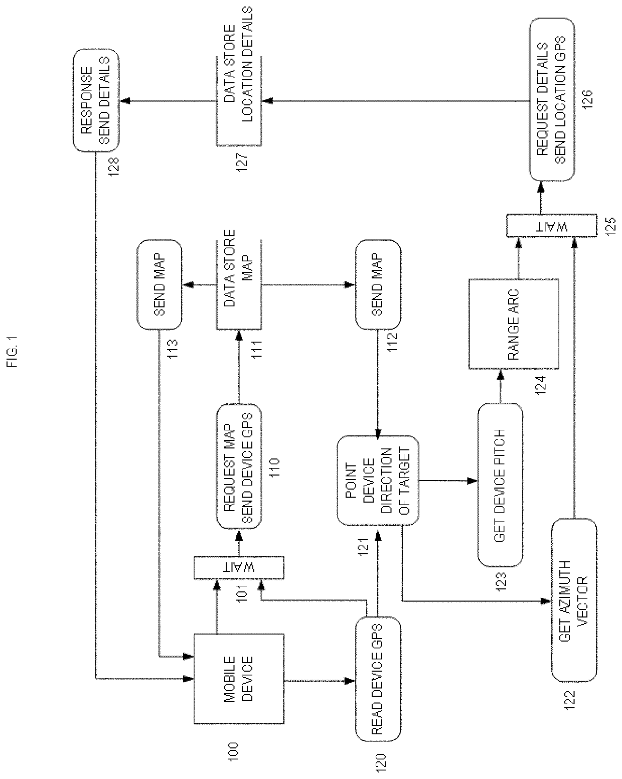
[0091]FIG. 1 is a block diagram illustrating a system overview showing an exemplary flow of the logical function implemented in the communication between the mobile device and the data store. It starts with the mobile device 100 and reads the GPS location of the device 120. With a GPS location 101, a request is made for a map 110 based on said GPS location. The data store queries for a map 111 centered on the GPS location. The data store responds with a map 113. The map is displayed on the mobile device 100. The map. The map 113 is used on the mobile device to for the operator to identify what target is selected. FIG. 112 and FIG. 113 are the same map. FIG. 112 is a virtual representation of the map and FIG. 113 is a physical manifestation. The operator points the mobile device 121 in the direction of the target, using the map and or visual observation. The direction of the mobile device 122 is used to determine the azimuth. An azimuth vector is created, from the GPS location of the...


PUM


Abstract

Utilizing hardware in a mobile device, any object in sight or beyond, stationary or moving, can be identified. The steps include measuring the compass bearing that the mobile device is pointing and the device tilt. The intersection of the bearing line and a distance, as calculated by degrees of the tilt, indicates which object is selected. Using a data connection, the mobile device requests information about objects at the intersection. The data store responds with information about objects at the location and that information may be displayed or saved. Where a topographical map is displayed beneath the object, a GPS location is determined. The distance between the mobile device and the GPS location is based on the map scale, mobile device screen and GPS location of the mobile device. Tracking moving objects for identification is accomplished by maintaining the intersection on the object as it traverses the map.

Description

BACKGROUND OF THE INVENTION[0001]Until now there has been no application of a stationary mobile device for selecting objects beyond the line of sight. For both games and real world applications it would be very useful to incorporate this functionality, using established paradigms, of the remote control and unpowered missile parabolas. Hardware limitations have discouraged implementation. Mobile devices generally do not have the hardware to measure distances. Mobile device software technology is evolving from and console game devices. Device hardware is much more capable. This problem could not be addressed on a desktop computation device and pointing a portable computation device at a house is not intuitive.[0002]The challenge was identification of distance. Implementation of range finding with a mobile device can be accomplished using GPS, compass and device pitch. Utilizing a scale map and device sensors, GPS location, direction and pitch of the device direction can pinpoint a loc...

Claims


Application Information

Patent Timeline
IPC IPC(8): H04W4/02G06F16/29G06F16/245G01S19/13
CPCG01S19/13H04W88/02G06F16/245G06F16/29H04W4/026H04W4/023G01S19/14G01S19/51
Inventor ROTHSCHILD, SHIMON
Owner ROTHSCHILD SHIMON
Why Eureka
Try Eureka