Antenna device and display device comprising the same

a technology of display device and antenna device, which is applied in the direction of antenna earthing, substantially flat resonant elements, resonant antennas, etc., can solve the problems of increased thickness of antenna device, interference or disturbance of antenna driving, etc., and achieve the effect of improving grounding reliability and increasing the thickness of antenna devi

Active Publication Date: 2020-12-24
DONGWOO FINE CHEM CO LTD +1
View PDF0 Cites 1 Cited by
  • Summary
  • Abstract
  • Description
  • Claims
  • Application Information

AI Technical Summary

Benefits of technology

[0024]According to exemplary embodiments of the present invention, an upper electrode and a lower electrode of an antenna device may be connected to each other by a flexible circuit board. For example, a ground pad included in the upper electrode and the lower electrode serving as a ground layer may be connected to each other so that a grounding reliability may be improved without disturbance by an external noise. Further, a feeding may be efficiently performed to each of the upper electrode and the lower electrode through the flexible circuit board.
[0025]The flexible circuit board may connect the upper electrode and the lower electrode along a lateral portion of the antenna device without penetrating the antenna device. Thus, a mutual interference with an active or passive circuit structure of the display device may be suppressed without increasing a thickness of the antenna device.

Problems solved by technology

Accordingly, the antennas may be adjacent to various conductive structures, circuit structures and sensing structures of the display device within a limited space, and thus an antenna driving may be interfered or disturbed by external noises.
When forming the interconnecting structure, a thickness of the antenna may increase, and mutual interferences and noises with other pixel structures or sensing structures in the display device may be caused

Method used


Image

  • Antenna device and display device comprising the same
  • Antenna device and display device comprising the same
  • Antenna device and display device comprising the same

Examples


Embodiment Construction

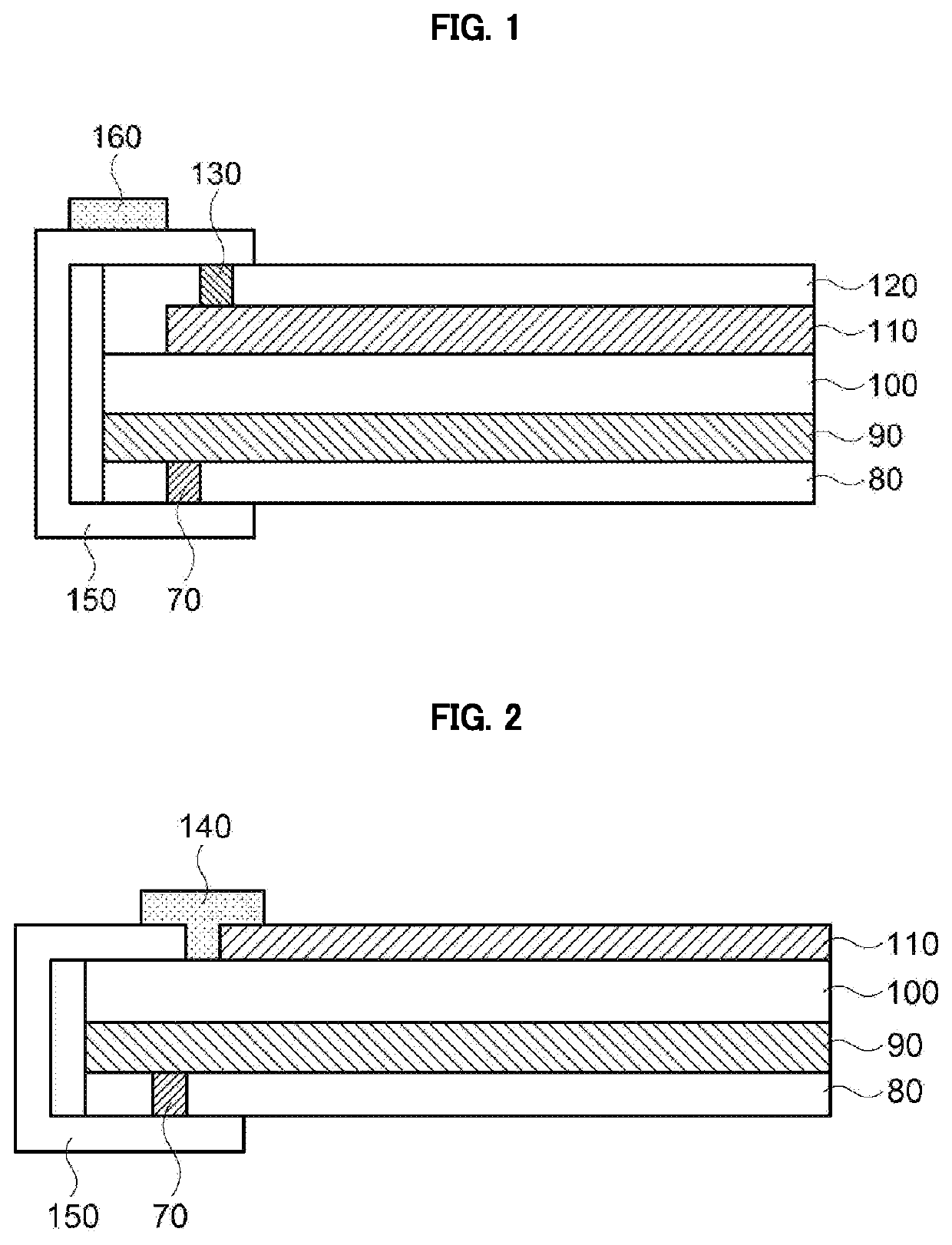
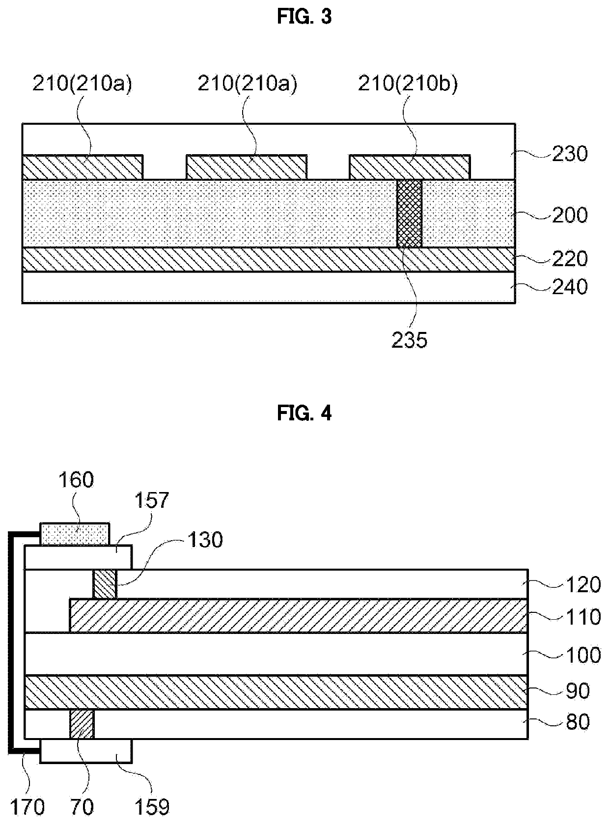
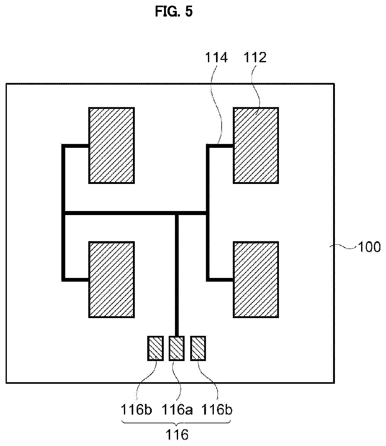
[0034]According to exemplary embodiments of the present invention, there is provided an antenna device including a first electrode layer and a second electrode layer with a dielectric layer interposed therebetween, and including a flexible circuit board (e.g., Flexible Printed Circuit Board (FPCB)) that connects the first electrode layer and the second electrode layer with each other.

[0035]The antenna device may be, e.g., a microstrip patch antenna fabricated in the form of a transparent film. For example, the antenna device may be applied to a device for high frequency band or ultra-high frequency band (e.g., 3G, 4G, 5G or more) mobile communications.

[0036]According to exemplary embodiments of the present invention, there is also provided a display device including the antenna device. However, an application of the antenna device is not limited to the display device, and the antenna device may be applied to various objects or structures such as a vehicle, a home electronic applianc...


PUM

PropertyMeasurementUnit
dielectric constantaaaaaaaaaa
flexibleaaaaaaaaaa

Abstract

An antenna device according to an embodiment of the present invention includes a dielectric layer, a first electrode layer disposed on a top surface of the dielectric layer, the first electrode layer including a radiation pattern, a second electrode layer disposed on a bottom surface of the dielectric layer, and a flexible circuit board connecting the first electrode layer and the second electrode layer with each other along a lateral portion of the dielectric layer. Efficiency of grounding and noise removing may be improved by the flexible circuit board.

Description

CROSS REFERENCE TO RELATED APPLICATIONS AND CLAIM OF PRIORITY[0001]The present application is a continuation application to International Application No. PCT / KR2019 / 002521 with an International Filing Date of Mar. 5, 2019, which claims the benefit of Korean Patent Application No. 10-2018-0026381 filed on Mar. 6, 2018 at the Korean Intellectual Property Office, the disclosures of which are incorporated by reference herein in their entirety.BACKGROUND1. Field[0002]The present invention relates to an antenna device and a display device including the same. More particularly, the present invention relates to an antenna device including an electrode and a dielectric layer and a display device including the same.2. Description of the Related Art[0003]As information technologies have been developed, a wireless communication technology such as Wi-Fi, Bluetooth, etc., is combined with a display device in, e.g., a smartphone form. In this case, an antenna may be combined with the display devic...

Claims


Application Information

Patent Timeline
Patent Type & Authority Applications(United States)
IPC IPC(8): H01Q9/04H01Q1/48H01Q1/24
CPCH01Q9/0407H01Q21/065H01Q1/48H01Q1/243H01Q1/38
Inventor HUH, YOON HORYU, HAN SUBCHOI, BYUNG JINHONG, WON BIN
Owner DONGWOO FINE CHEM CO LTD
Why Eureka
Try Eureka