
Electroacoustic Transducer for the Parametric Generation of Ultrasound

a technology of ultrasound and electroacoustic transducers, applied in the field of acoustic measurements, can solve the problems of low reliability and stability of piezoelectric transducers of parametric source operation, incomplete compliance with operation, and decrease of signal-to-noise ratio at the receiver input, and achieve the effect of increasing the sound pressure amplitud

Active Publication Date: 2020-12-17
OOO GIDROMARINN
View PDF0 Cites 0 Cited by
  • Summary
  • Abstract
  • Description
  • Claims
  • Application Information

AI Technical Summary

Benefits of technology

The technical effect of this patent is to expand the capabilities of a device by making it able to generate calibration sound waves in a nonlinear aquatic environment in a wide range of changes in sound pressure levels. This improves the accuracy of measurements and reduces the difficulty of getting results due to masking noise levels. The invention uses an electro-acoustic transducer for parametric generation of ultrasound, which increases the sound pressure amplitude of acoustic signals formed in nonlinear aquatic environments, which are used as calibration signals during hydroacoustic measurements.

Problems solved by technology

The disadvantages of the analogue include low reliability and stability of piezoelectric transducer of a parametric source operation, besides, noise immunity of measurements carried out in a hydroacoustic basin is insufficient, which leads to incomplete compliance with operational requirements
As a result, when conducting quantitative measurements, the signal-to-noise ratio at the receiver input decreases;cavitation phenomena, generating strong hydrodynamic disturbances (see Ultrasound.
The well-known acoustic parametric emitter also has insufficient compliance with operational requirements, in particular, the reliability and stability of the piezoelectric transducer of a parametric source is low, the generation of calibration sound vibrations of sound pressure in a small range of operating differential frequency signals is low F=|ƒ2−ƒ1|.
400);the device does not provide the possibility of changing the relative position of two identical piezoelectric transducers with a flat disk piezoelectric element with a radius of (d / 2) each, which does not allow to regulate the generation efficiency of calibration signals, the sound pressure levels of which are directly proportional to both the product of the amplitudes and the number of pump wavelengths that fall within the “common extent” of the region of mutual overlapping (see Voloshchenko V. Yu., Timoshenko V. I. Parametric sonar aids of the near underwater observation (part 1)—Taganrog; Publishing house of TTI SFU, 2009. p.
The disadvantage of the measuring emitter according to the prototype is the lack of compliance with operational requirements, in particular, the range of operating frequencies of calibration signals in the low-frequency region is limited, the conversion coefficient of the generated signal of the difference signal from ultrasonic pump signals is reduced, the specific acoustic power of the pump signals is not provided in the aquatic environment, etc.
Below, in greater details some of the reasons and consequences of the specified mismatch of the prototype with operational requirements are considered:low generation efficiency of calibration sound vibrations due to the use of a piezoelectric transducer, the radiating aperture of which is a portion of a convex spherical surface.
Thus, the general disadvantages of the prototype and the above analogues include insufficient compliance with operational requirements, in particular, a reduced conversion coefficient of the generated differential signal from ultrasonic pump signals, a limited range of operating frequencies of calibration signals to the low-frequency region, since only the spectral components of the differential frequency are used, insufficient energy potential, characterized by the acoustic power of its radiation per unit the area of the convex spherical aperture, the reliability and stability of the piezoelectric transducer are low.

Method used


Image

  • Electroacoustic Transducer for the Parametric Generation of Ultrasound
  • Electroacoustic Transducer for the Parametric Generation of Ultrasound

Examples


Embodiment Construction

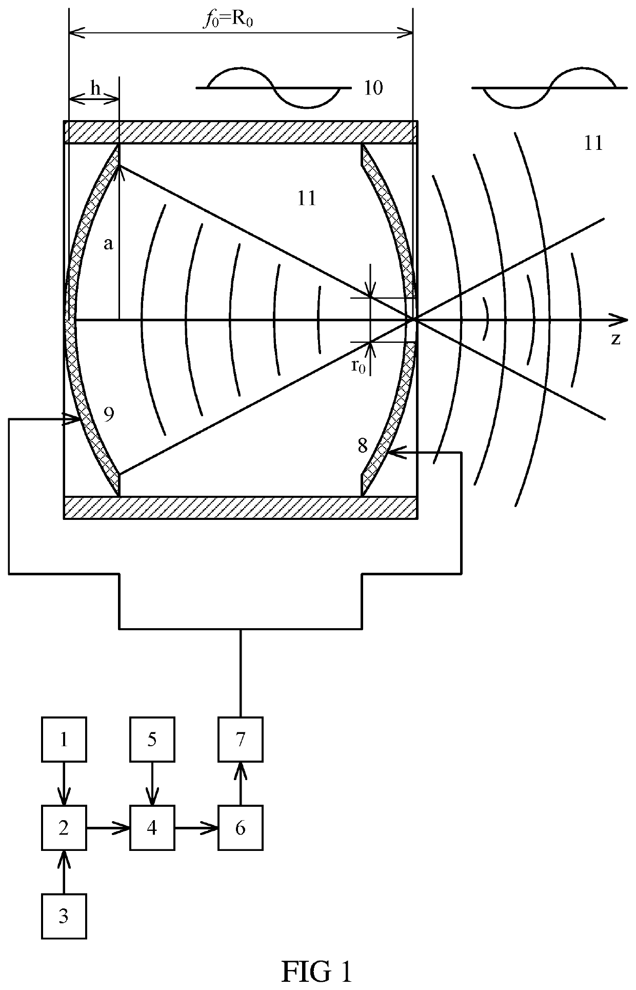
[0043]The electro-acoustic transducer for parametric generation of ultrasound contains (FIG. 1) the first 1 and second 3 electric oscillation generators, the outputs of which are through a linear adder 2, a pulse modulator 4, controlled by a pulse generator 5, as well as a power amplifier 6 and a notch filter 7 are connected to the inputs of the first a piezoelectric transducer 8 with a convex spherical surface of the aperture and a second piezoelectric transducer 9 with a concave spherical surface of the aperture, and the supporting structure of the cylinder 10, which combines piezoelectric transducers 8 and 9. The supporting structure 10 provides the possibility of a centered change in the distance between the piezoelectric transducers 8 and 9, moreover, for both piezoelectric transducers, the diameters D of apertures, the average wavelength λ for the range of emitted pump signals, the curvature radii R0, focal lengths F0, focal spot radii r0 are the same and are related by the re...


PUM


Abstract

The construction has two piezoelectric transducers with radiating apertures shaped as sections of spherical surface one is concave, the second is convex, of sufficient wave sizes D / λ>10, where D is the diameter of the aperture, λ is the wavelength of the emitted pump signal). For each piezoelectric transducers radii of curvature R0, focal lengths F0 and focal spots radii r0 with a wave length of radiated signal are the same and are related by r0×R0=0.61×λ×F0. Piezoelectric transducers with radiating apertures shaped as sections of spherical surface are provided with shielding elements, hydro-, electric- and noise insulation and one of them with convex aperture is made with an open axial hole with radius r=(2÷3)×r0 in the central part of the convex spherical surface of the aperture.

Description

RELATED APPLICATIONS[0001]This Application is a Continuation application of International Application PCT / RU2018 / 000861, filed on Dec. 24, 2018, which in turn claims priority to Russian Patent Application RU2017146766, filed Dec. 28, 2017, both of which are incorporated herein by reference in their entirety.FIELD OF THE INVENTION[0002]The invention relates to the field of acoustic measurements, in particular to sound pressure measuring emitters, which are used as a source of sound vibrations in a hydroacoustic pool, and their spectral composition is determined by both their own resonant passband and the redistribution of powerful pump signals radiated, i.e. effects of both self-interaction and interaction arising from the propagation of acoustic waves of finite amplitude due to the nonlinearity of the elastic properties of aquatic environment.BACKGROUND OF THE INVENTION[0003]At present, in hydroacoustic measurements as measuring emitters of sound pressure, mainly cylindrical and dis...

Claims


Application Information

Patent Timeline
Patent Type & Authority Applications(United States)
IPC IPC(8): H04R17/10
CPCH04R17/10H04R2217/03B06B1/0644B06B1/0215B06B2201/55H04R17/00
Inventor VOLOSHCHENKO, VADIM YU.TARASOV, SERGEY P.PLESHKOV, ANTON YU.VORONIN, VASILIY A.PIVNEV, PETR P.VOLOSHCHENKO, ALEKSANDR P.GRIVTSOV, VLADIMIR V.
Owner OOO GIDROMARINN
Learn More