Photon-counting computed tomography

a computed tomography and photon counting technology, applied in the field of image signal processing system, can solve the problems of weak spectral performance and other problems, and achieve the effects of increasing spectral performance, increasing spectral performance, and maintaining rate performan

Active Publication Date: 2020-12-17
KONINKLJIJKE PHILIPS NV
View PDF0 Cites 3 Cited by
  • Summary
  • Abstract
  • Description
  • Claims
  • Application Information

AI Technical Summary

Benefits of technology

The patent describes a system for processing photon counting data from detectors in an X-ray imaging apparatus. The system allows for improved spectral performance in detectors with large pixel size. By using multiple calibration curves from different bins, the system can secure optimal estimates of the effective path length and maintain or improve rate performance in certain image positions. The system also allows for good quality path length data to be produced from the detector.

Problems solved by technology

However, in such systems, weaker spectral performance is one of the consequences because of an increase in charge sharing events.

Method used


Image

  • Photon-counting computed tomography
  • Photon-counting computed tomography
  • Photon-counting computed tomography

Examples


Embodiment Construction

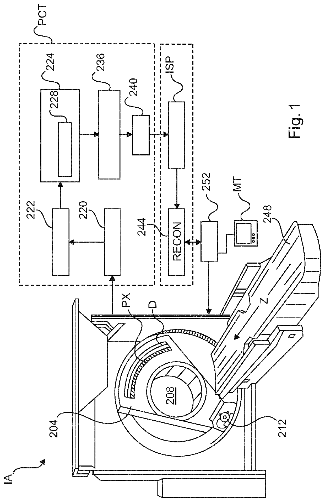
[0050]With reference to FIG. 1, there is shown a spectral imaging arrangement 100. The spectral imaging arrangement includes in one embodiment (but not necessarily all embodiments) a computed tomography (CT) system having a rotatable gantry portion 204 that is rotatable about an examination region 208 around a longitudinal or z-axis.

[0051]An x-ray source 212, such as an x-ray tube, is supported by the rotating gantry portion 204 and emits a multi-energetic radiation beam or photons that traverse the examination region 208 from different projection directions whilst the gantry is in rotation.

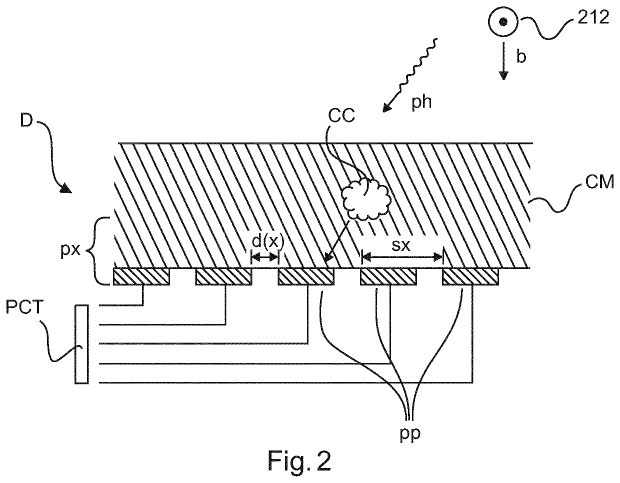
[0052]An X-radiation sensitive detector D includes one or more sensors or pixels px. Each pixel px is capable of detecting photons emitted by the source 212 that traverse the examination region 208. Broadly, each pixel px generates electrical signals, such as electrical currents or voltages, which are indicative of the respective detected photons. This detection process will be described in more ...


PUM

PropertyMeasurementUnit
pixel sizeaaaaaaaaaa
photon countingaaaaaaaaaa
photon counting detectoraaaaaaaaaa

Abstract

An image signal processing system (ISP) comprising an input interface (IN) for receiving photon counting projection data acquired by an X-ray imaging apparatus (IA) having a photon counting detector (D). A calibration data memory (CMEM) of the system holds calibration data. The calibration data encodes photon counting data versus path lengths curves for different energy thresholds of i) said detector (D) or ii) of a different detector. At least one of said curves is not one-to-one. A path length convertor (PLC) of the system converts an entry in said photon counting projection data into an associated path length based on said calibration data.

Description

FIELD OF THE INVENTION[0001]The invention relates to an image signal processing system, to imaging systems, to an image signal processing method, to a computer readable medium, to a computer program element and to the computer readable medium.BACKGROUND OF THE INVENTION[0002]X-ray based imaging is an important tool in various fields of endeavor, such as medical.[0003]In the medical field, more traditional X-ray systems use energy integrating detectors where the spectral information inherent in the detected x-ray radiation is essentially ignored. This situation has been improved with the advent of photon counting detector systems that are capable of resolving the energy in the detected radiation into spectral energy components to so enhance information content extraction.[0004]The pixel size (pixel pitch) as used in photon counting detectors has an effect on the rate performance. In particular, the smaller the pixel size, the better the rate performance. A pixel size of about 200 mic...

Claims


Application Information

Patent Timeline
Patent Type & Authority Applications(United States)
IPC IPC(8): A61B6/00G01N23/046G01N23/083G06T11/00
CPCG01N2223/401G06T11/003G01N23/083A61B6/4241G01N23/046A61B6/482A61B6/585G01N2223/303G01N2223/505A61B6/5258G01T1/17G01T1/2928
Inventor ROESSL, EWALDSTEADMAN, ROGERHERRMANN, CHRISTOPHPROKSA, ROLAND
Owner KONINKLJIJKE PHILIPS NV
Why Eureka
Try Eureka