Reversible dual-position electric connector
a dual-position, electric connector technology, applied in the direction of coupling devices, two-part coupling devices, electrical apparatus, etc., can solve the problems of high manufacturing cost of bidirectional electrical connectors, low reliability of functions, and failure of docking between electrical plugs and electrical receptacles, so as to reduce manufacturing and assembly costs
- Summary
- Abstract
- Description
- Claims
- Application Information
AI Technical Summary
Benefits of technology
Problems solved by technology
Method used
Image
Examples
first embodiment
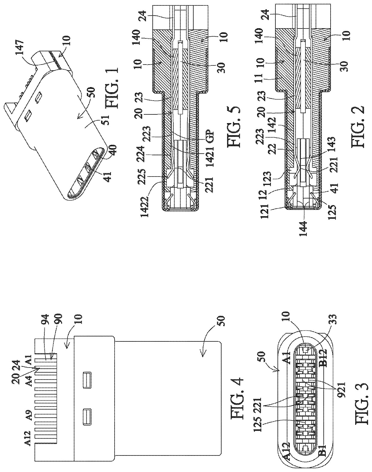
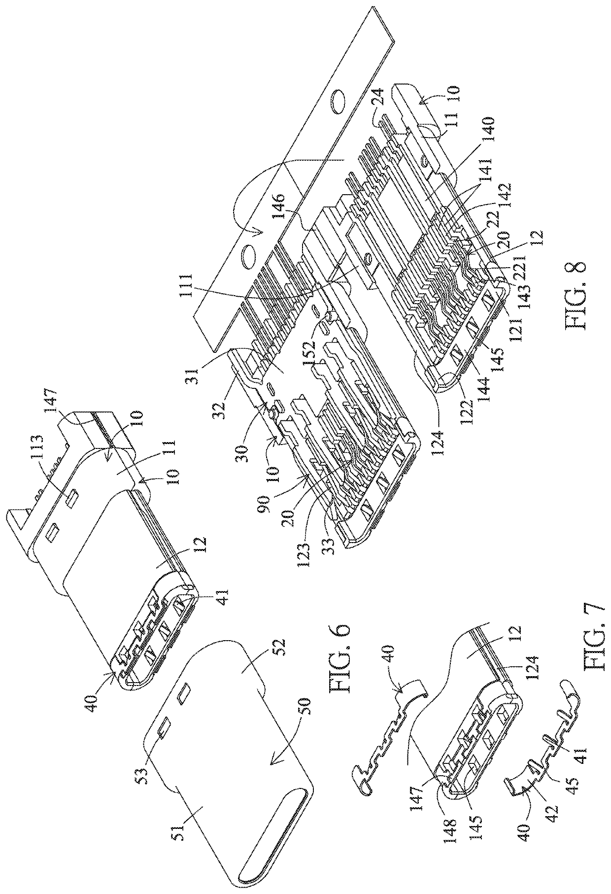
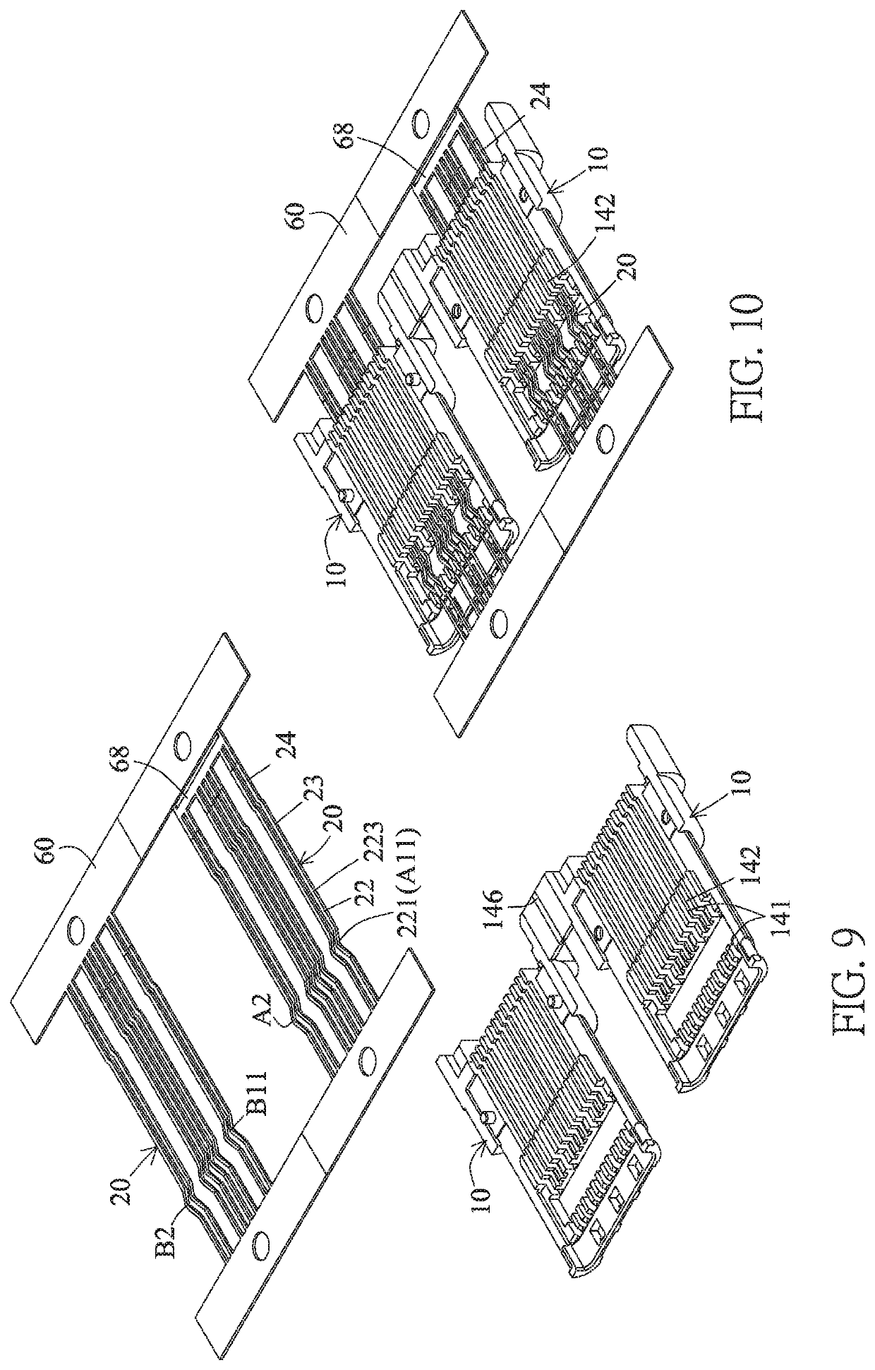
[0082]Referring to FIGS. 1 to 16, a bidirectional duplex USB TYPE-C 3.0 electrical plug according to the invention includes two insulation seats 10, two rows of contacts, a metal partition plate 30, two ground members 40, and a metal housing 50.
[0083]The insulation seat 10 is integrally provided with a base portion 11 and a docking portion 12. The docking portion 12 is connected to the front end of the base portion 11. The inner surfaces of the base portions 11 of the two insulation seats are provided with connection surfaces 111 resting against each other. One of the insulation seats is provided with an engagement hole 151 engaging with an engagement column 152 of the other insulation seat. The rear section of the base portion 11 is higher than the front section thereof and the outer surface of the rear section is provided with an engagement block 113. The docking portion 12 is provided with a baseplate 121 and two side plates 122. The two side plates 122 are connected to left and ...
second embodiment
[0131]The manufacturing method of this embodiment is substantially the same as the second embodiment except for the difference that this embodiment has no ground member, and the pins 24 of the upper and lower terminals 20 are in the form of one horizontal row of members flush with each other, wherein the pins 24 of the four pairs of terminals A1 / B12, A4 / B9, A9 / B4 and A11 / B1 are in an horizontal equal-height and parallel manner or adjacent and close to each other.
[0132]Referring to FIGS. 46 to 49 showing the first modified implementation of the third embodiment of the invention, this embodiment is a bidirectional duplex USB TYPE-C 2.0 electrical plug is substantially the same as the third embodiment except for the difference that the base portion 11 of the lower insulation seat 10 of this embodiment extends backwards and projects to form a bonding plate 114 as compared with the base portion of the upper insulation seat 10, wherein the bonding plate 114 is provided with one row of pin...
fifth embodiment
[0137]Referring to FIGS. 59 and 60 according to the invention, this embodiment provides a flash drive 500 having the electrical connector of the invention. The flash drive 500 includes an outer housing 230, a circuit board 240, an electronic device 250 and an electrical connector 3.
[0138]The circuit board 240 is provided with multiple electroconductive connection points and multiple printed circuits (not shown).
[0139]The electronic device 250 is electrically connected to the circuit board 240. The electronic device 250 includes an electronic unit 251, a control chip 252 and a circuit safety protection device 253. The electronic unit 251 is the main configuration of the electronic device 250, and is a storage unit, which may be a memory, in this embodiment.
[0140]The control chip 252 controls the operation of the electronic unit 251. The circuit safety protection device 253 includes multiple circuit safety protection elements, such as the power safety control chip, anti-over-current e...
PUM
 Abstract
Description
Claims
Application Information
 - R&D
- Intellectual Property
- Life Sciences
- Materials
- Tech Scout
- Unparalleled Data Quality
- Higher Quality Content
- 60% Fewer Hallucinations
Browse by: Latest US Patents, China's latest patents, Technical Efficacy Thesaurus, Application Domain, Technology Topic, Popular Technical Reports.
© 2025 PatSnap. All rights reserved.Legal|Privacy policy|Modern Slavery Act Transparency Statement|Sitemap|About US| Contact US: help@patsnap.com


