
Distributed pose estimation

a distribution and pose technology, applied in the field of pose estimation technologies, can solve the problems of limiting the performance and scalability of tracking and localization applications that rely on pose information, mapping algorithms can impose significant power and resource demands on devices, visual and inertial tracking, computational complexity of pose estimation, etc., to achieve the effect of reducing the cost of equipmen

Active Publication Date: 2020-11-19
QUALCOMM INC
View PDF0 Cites 34 Cited by
  • Summary
  • Abstract
  • Description
  • Claims
  • Application Information

AI Technical Summary

Benefits of technology

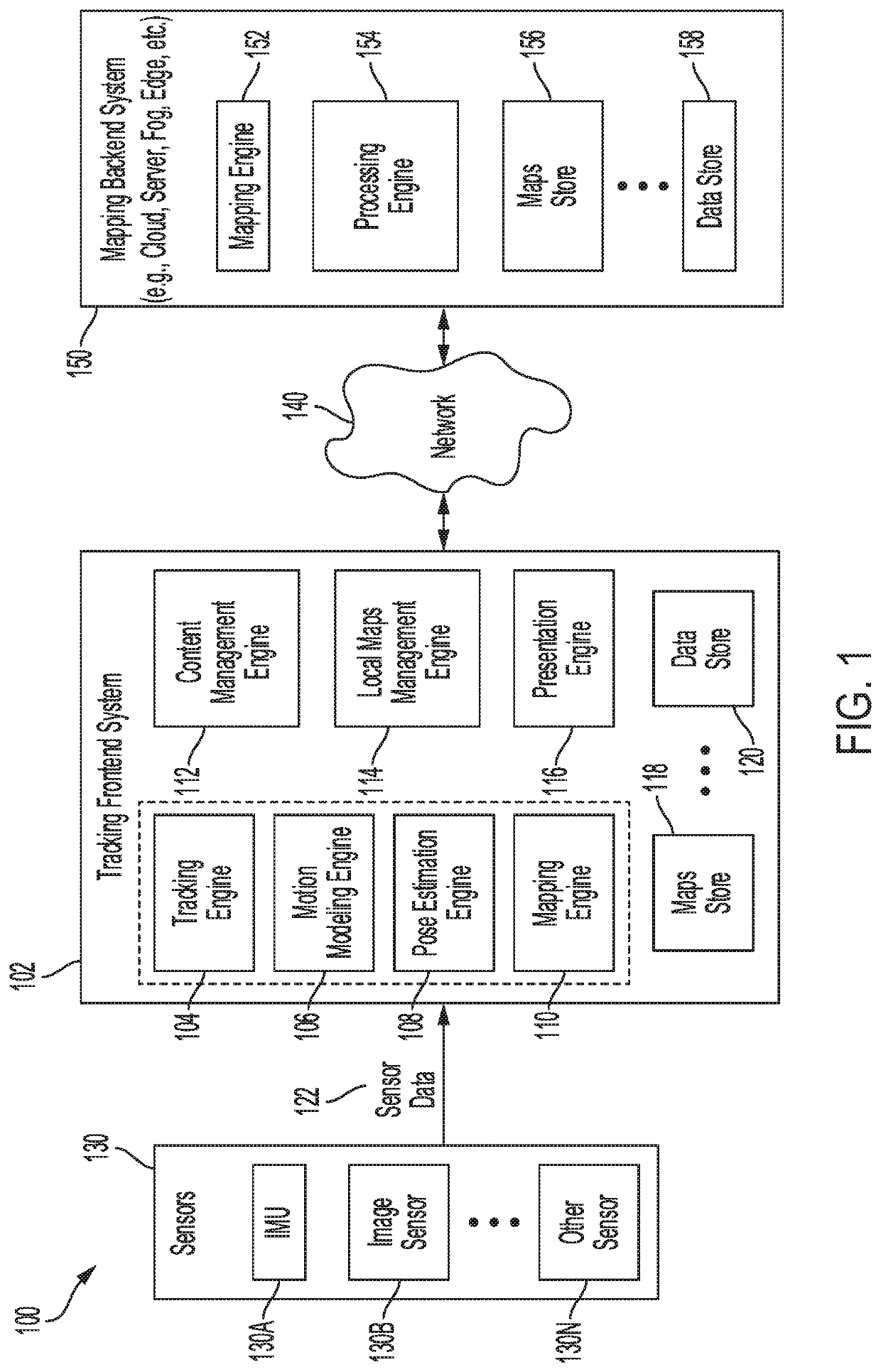
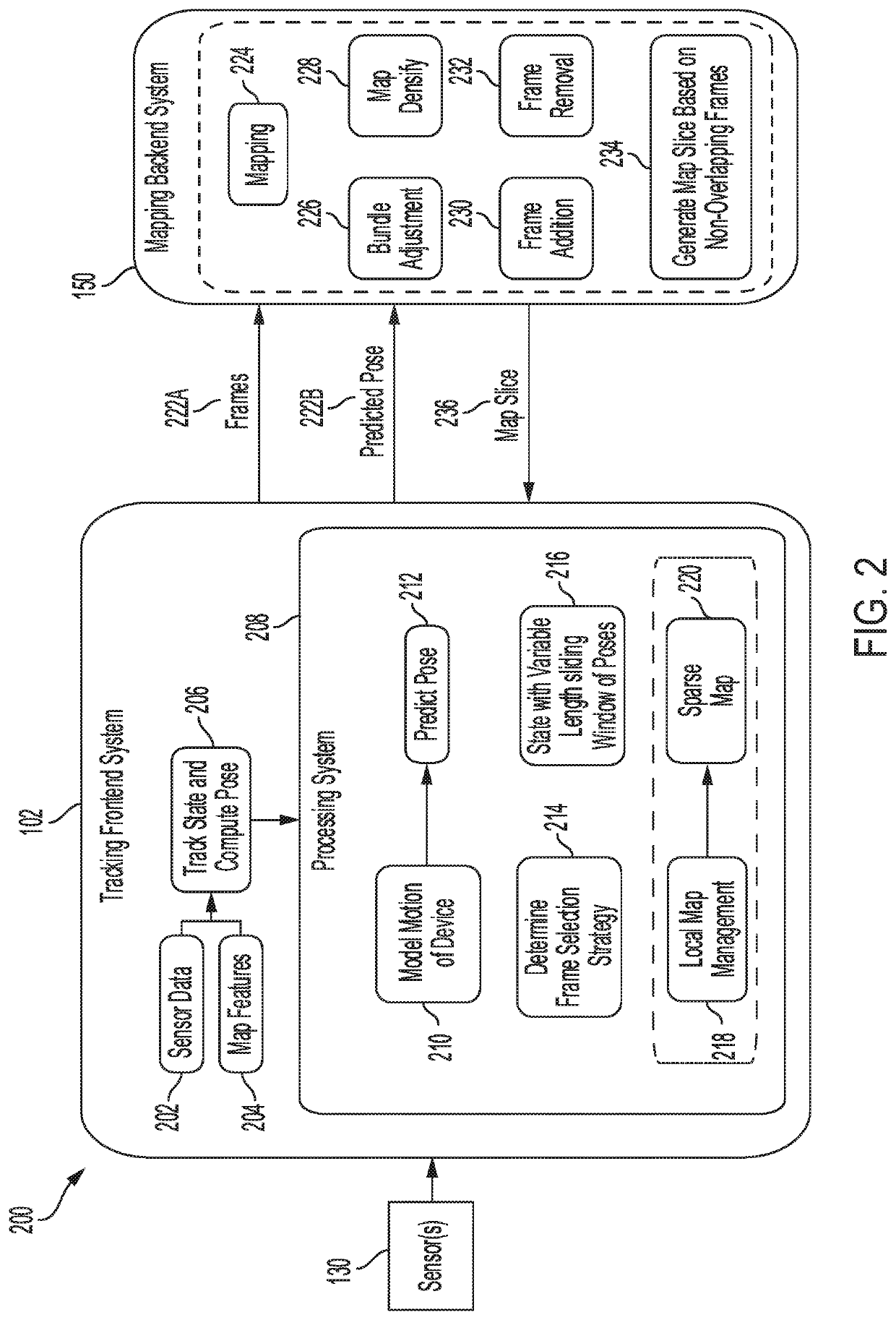
The patent describes a system and method for reducing the power and resource requirements of pose estimation, tracking, and localization applications. It suggests using split tracking, mapping, and sophisticated algorithm engines to achieve this. By distributing the functions across different devices, the system can reduce the computational load and enable smaller, lighter, and more comfortable devices to implement these technologies. The system also suggests using a tracking frontend and a mapping backend to further improve efficiency and accuracy. Overall, the patent provides a solution to the challenges of implementing these technologies in resource-constrained devices.

Problems solved by technology

As noted above, the computational complexity of pose estimation systems can impose significant power and resource demands, can be a limiting factor in various applications, and can also limit the performance and scalability of tracking and localization applications that rely on pose information.
For example, the computational complexity of pose estimation, visual and inertial tracking, and mapping algorithms can impose significant power and resource demands on devices in tracking and localization applications, particularly in large scale environments.

Method used


Image

  • Distributed pose estimation
  • Distributed pose estimation
  • Distributed pose estimation

Examples


Embodiment Construction

[0032]Certain aspects and embodiments of this disclosure are provided below. Some of these aspects and embodiments may be applied independently and some of them may be applied in combination as would be apparent to those of skill in the art. In the following description, for the purposes of explanation, specific details are set forth in order to provide a thorough understanding of embodiments of the application. However, it will be apparent that various embodiments may be practiced without these specific details. The figures and description are not intended to be restrictive.

[0033]The ensuing description provides example embodiments only, and is not intended to limit the scope, applicability, or configuration of the disclosure. Rather, the ensuing description of the exemplary embodiments will provide those skilled in the art with an enabling description for implementing an exemplary embodiment. It should be understood that various changes may be made in the function and arrangement ...


PUM


Abstract

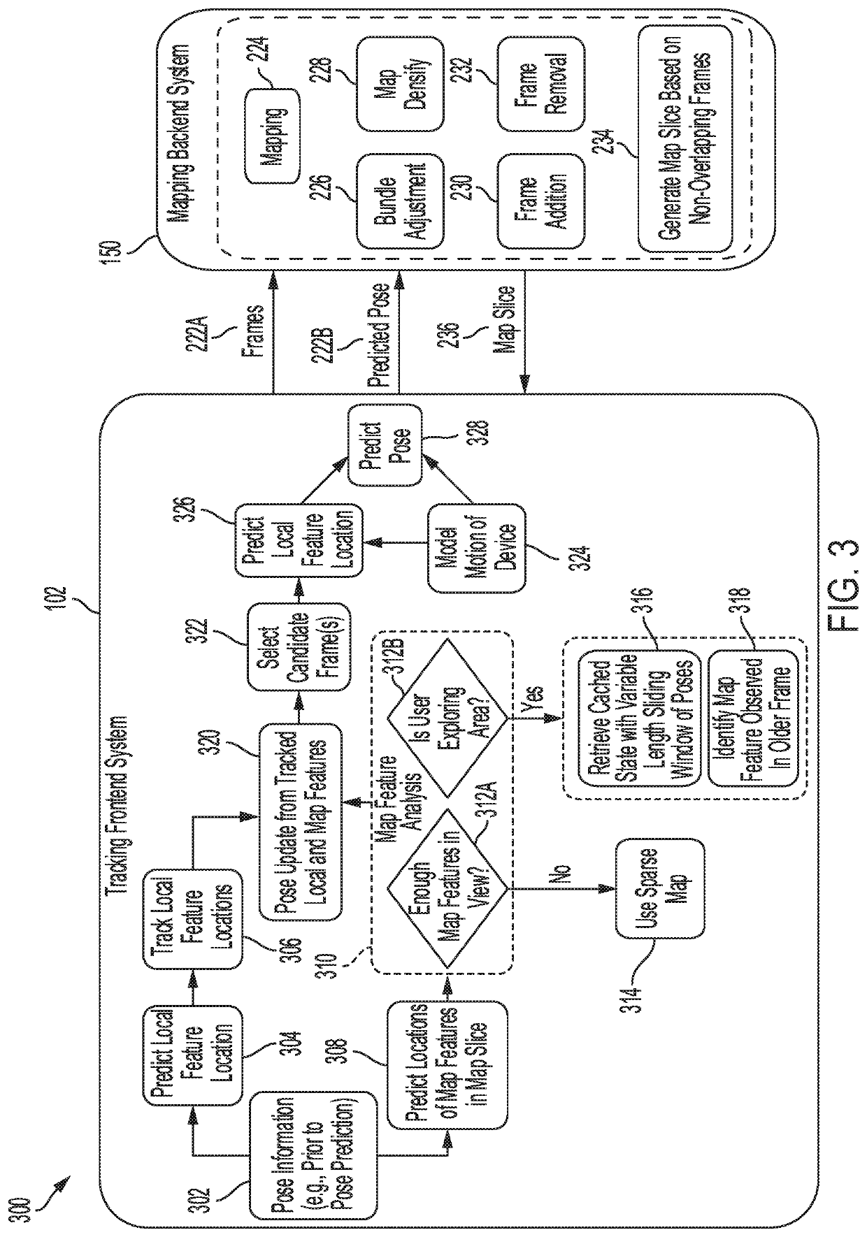
Systems, methods, and computer-readable media are provided for distributed tracking and mapping for extended reality experiences. An example method can include computing, at a device, a pose of the device at a future time, the future time being determined based on a communication latency between the device and a mapping backend system; sending, to the mapping backend system, the pose of the device; receiving, from the mapping backend system, a map slice including map points corresponding to a scene associated with the device, the map slice being generated based on the pose of the device, wherein the map points correspond to the predicted pose; and computing an updated pose of the device based on the map slice.

Description

TECHNICAL FIELD[0001]The present disclosure generally relates to pose estimation technologies.BACKGROUND[0002]Pose estimation can be used in various applications, such as computer vision and robotics, to determine the position and orientation of a human or object relative to a scene or environment. This pose information can be used to manage interactions between a human or object and a specific scene or environment. For example, the pose (e.g., position and orientation) of a robot can be used to allow the robot to manipulate an object or avoid colliding with an object when moving about a scene. As another example, the pose of a user or a device worn by the user can be used to enhance or augment the user's real or physical environment with virtual content. However, the computational complexity of pose estimation systems can impose significant power and resource demands, and can be a limiting factor in various applications. The computational complexity of pose estimation can also limi...

Claims


Application Information

Patent Timeline
Patent Type & Authority Applications(United States)
IPC IPC(8): G06T7/73G06T19/00G06F3/01G06F3/00G02B27/01
CPCG06F3/005G02B27/017G02B2027/0187G02B27/0179G06F3/012G06T19/006G06T7/75G06T2207/30244G06F3/011G02B2027/0178G02B27/0093G02B2027/0138
Inventor CHOUDHURI, CHIRANJIBGORUR SHESHAGIRI, PUSHKARGUPTE, AJIT DEEPAKMELKOTE KRISHNAPRASAD, VINAYSHARMA, CHAYANRAO, AJIT VENKAT
Owner QUALCOMM INC
Learn More