Bearing arrangement for a wind turbine and wind turbine

Inactive Publication Date: 2020-11-19
SIEMENS GAMESA RENEWABLE ENERGY AS
View PDF0 Cites 0 Cited by
  • Summary
  • Abstract
  • Description
  • Claims
  • Application Information

AI Technical Summary

Benefits of technology

The patent text discusses a new way of integrating an axial bearing in a wind turbine to prevent leakage and reduce maintenance costs. The goal is to create a simpler and more efficient bearing arrangement for wind turbines.

Problems solved by technology

However, current solutions, e.g. a bolt connection between the axial collar of an axial bearing and the drive shaft, have a leakage potential, are cumbersome in their manufacture and difficult to service.

Method used


Image

  • Bearing arrangement for a wind turbine and wind turbine
  • Bearing arrangement for a wind turbine and wind turbine
  • Bearing arrangement for a wind turbine and wind turbine

Examples


Embodiment Construction

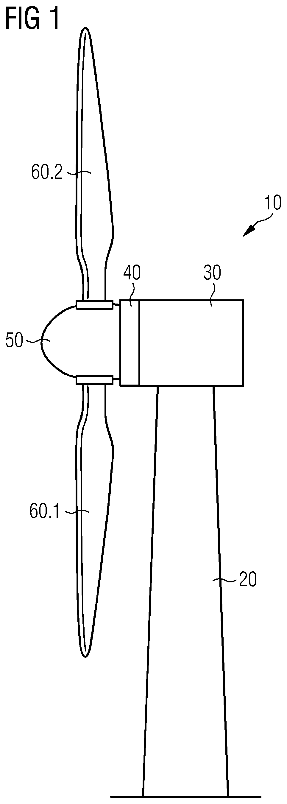
[0033]FIG. 1 shows a side view on a wind turbine 10. The wind turbine 10 comprises a supporting tower 20 and a nacelle 30, whereby the nacelle 30 is attached to the supporting tower 20. The nacelle 30 comprises a bearing arrangement 70, which is not shown in FIG. 1 but can be seen in FIG. 2. The wind turbine 10 further comprises a generator 40 attached to a rotor 50 of the wind turbine 10. Two wind turbine blades 60.1, 60.2 are attached to the rotor 50.

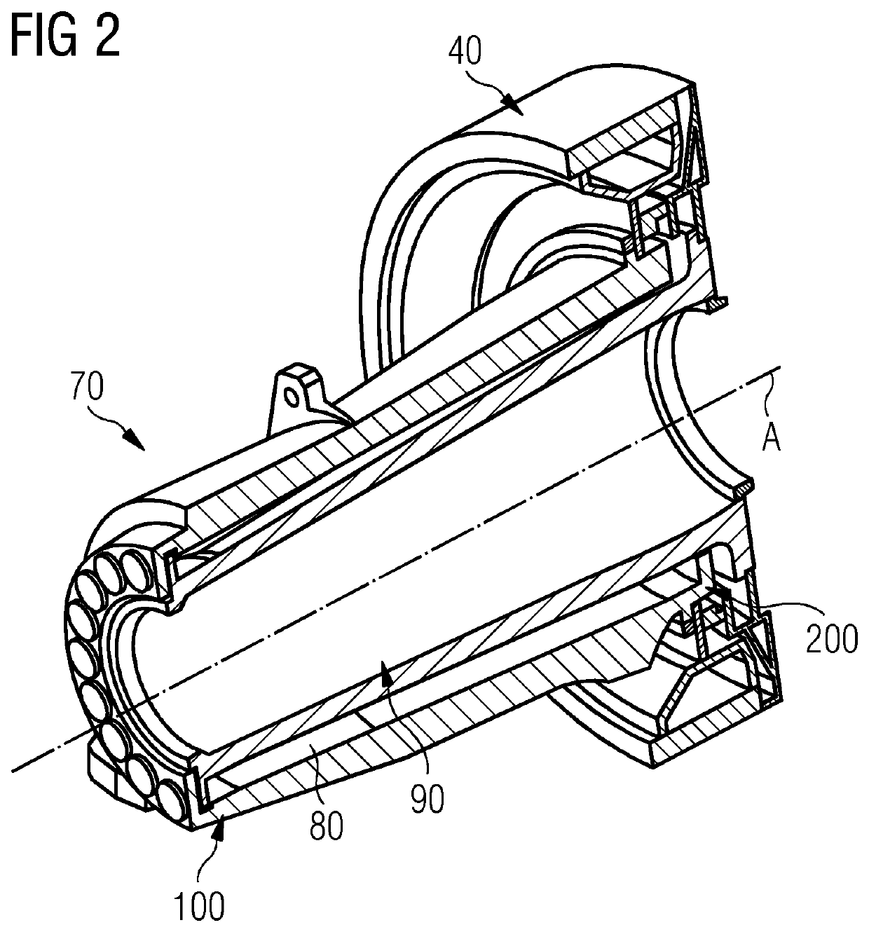
[0034]FIG. 2 shows a side perspective view on a sectional cut along the longitudinal axis A of the bearing arrangement 70 of the wind turbine 10 of FIG. 1. The bearing arrangement 70 comprises a bearing housing 80 and a drive shaft 90, whereby the drive shaft 90 is arranged within the bearing housing 80 in an axial direction along the longitudinal axis A of the bearing housing 80 as indicated in FIG. 2. The longitudinal axis A of the bearing housing 80 corresponds to the longitudinal axis A of the drive shaft 90 and thereby is a longi...


PUM


Abstract

Provided is a bearing arrangement for a wind turbine c including a bearing housing and a drive shaft, whereby the drive shaft is arranged within the bearing housing in an axial direction along a longitudinal axis of the bearing housing, the bearing arrangement further including a downwind bearing and an upwind bearing as radial fluid bearings, whereby the downwind bearing and the upwind bearing are arranged between the bearing housing and the drive shaft, the bearing arrangement further including an axial bearing. The axial bearing includes an axial collar, whereby the axial collar is integrally formed with the drive shaft.

Description

CROSS-REFERENCE TO RELATED APPLICATIONS[0001]This application claims priority to European Application No. 19174867.2, having a filing date of May 16, 2019, the entire contents of which are hereby incorporated by reference.FIELD OF TECHNOLOGY[0002]The following relates to a bearing arrangement for a wind turbine and a wind turbine.BACKGROUND[0003]In general, bearing arrangements of wind turbines comprise a bearing housing and a drive shaft, whereby the drive shaft is arranged within the bearing housing in an axial direction along a longitudinal axis of the bearing housing. Bearings of the bearing arrangement are arranged about the drive shaft, so that the drive shaft can be rotated within the bearing housing by means of a rotor of the wind turbine. Such a bearing arrangement is known from EP 3 276 192 A1, for example.[0004]The bearing arrangement must be provided with axial load taking capabilities to be able to take an axial load from an axial or thrust force of the drive shaft. Suc...

Claims


Application Information

Patent Timeline
IPC IPC(8): F03D80/70F16C32/06
CPCF16C32/0633F03D9/25F03D80/70F16C2360/31F05B2240/52F05B2240/53F16C17/08F05B2240/57F05B2260/603F05B2260/98F16C17/03F16C17/107F16C17/26F03D15/00Y02E10/72
Inventor BAK, FRANKDEMISSIE, EDOMKANSTRUP, TROELSMICHAELSEN, CLAUSSOERENSEN, MORTEN
Owner SIEMENS GAMESA RENEWABLE ENERGY AS
Why Eureka
Try Eureka