Vacuum sponge drainage

a technology of vacuum sponge and sponge, which is applied in the field of vacuum sponge unit, can solve the problems of problematic use and application field of the device, and achieve the effect of simplifying guidan

Pending Publication Date: 2020-11-19
LOHMANN & RAUSCHER
View PDF0 Cites 4 Cited by
  • Summary
  • Abstract
  • Description
  • Claims
  • Application Information

AI Technical Summary

Benefits of technology

[0041]The invention is to be used in those cases in which repeated, short-term surgery is to be expected due to septic conditions (“relaparotomies”). The inventive device must normally be inserted and removed under conventional operative conditions (i.e., body cavity opened by incision). Its application will initially be limited to severe septic syndromes, as there is a risk of organs being iatrogenically injured by direct suction at the sponge. After the abdomen has been opened, the vacuum sponge drainage unit is precisely placed and the abdominal cavity is subsequently closed with a suture so that suction can be reestablished by the cavity being closed again. It is also possible for the invention to be used in combination with an air-tight film dressing to close the abdominal cavity. Placement of the inventive device is also possible with minimal invasive surgery, e.g. laparoscopically. The invention can also be used in other body cavities, in the thoracic cavity, in infected cavities, in organ cavities, in tissue abscesses, intestinal lumina, etc.
[0042]Embodiments containing combinations of the features described in the foregoing are particularly preferred.
[0043]The channel is preferably disposed parallel to a longitudinal axis of the fluid collecting member. It is preferred that the fluid collecting member is circular or cylindrical in shape, in particular, and that the channel is disposed parallel to the cylindrical fluid collecting member. The longitudinal axis of the fluid collection member is preferably the axis that is oriented substantially parallel, when the fluid collection member is used in the intended manner, to the inner wall of the body region in which the fluid collecting member is disposed. It is further preferred that the channel is disposed along an axis of symmetry of the fluid collecting member. The fluid collecting member is preferably tubular, the channel being the inner cavity in the tubular fluid collecting member. It is preferred that the channel has a first opening as an inlet for the guide member and / or the delivery member, and a second opening as an outlet for the guide member and / or the delivery member. It is preferred that the first opening and the second opening are disposed on substantially opposite surfaces of the fluid collecting member. What this advantageously achieves is that the channel for guiding the guide member, in particular a guide wire, and / or for guiding the delivery member, in particular a probe unit and / or an endoscope, is used by the fluid collecting member such that the channel forms a connection between the proximal and distal ends of the fluid collecting member. When the channel is disposed symmetrically in the fluid collecting member, this creates the advantages that the fluid collecting member collapses in a particularly uniform manner about a drainage tube disposed in the channel, for example, if the drainage tube applies a negative pressure, that medicines which are supplied to the fluid collecting member via a delivery member disposed in the channel are distributed particularly uniformly in the fluid collecting member and on the surface thereof, and that guidance along the guide member is particularly simple, since the fluid collecting member is disposed at an identical radius about the guide member. When the channel is disposed outside the axis of symmetry of the channel, but parallel to it, this provides the advantages that a specific region of the body, in which the fluid collecting member is disposed when used in the intended manner and which is closer to the channel than the opposite intracorporeal region, can be exposed to the influences of negative pressure, administration of medicines, etc. more intensively than the opposite region. Disposing the channel parallel, and particular in a straight line, provides the advantage that the frictional force that arises when guiding the fluid collecting member along the guide member and when inserting the delivery member into the fluid collecting member can be advantageously reduced. In this way, moving the fluid collecting member in relation to the guide member and / or the delivery member is advantageously simplified.
[0044]The fluid collecting member preferably has a longitudinal slit along the longitudinal axis of the fluid collecting member, said longitudinal slit extending between the surface of the fluid collecting member and the channel. The longitudinal slit preferably extends between the distal end and proximal ends and over the entire length of the fluid collecting member. The longitudinal slit is preferably designed in the same way as the longitudinal slit of the overtube. The longitudinal slit preferably extends in the radial direction of the fluid collecting member between the channel and the surface of the fluid collecting member which is closest to the channel. A fluid collecting member with a longitudinal slit provides the advantage that it can be placed onto an endoscope, a guide member, a delivery member, etc. at any time and inserted into the body, without having to remove the endoscope or the like. What can also be advantageously achieved is that a fluid collecting member which is already in use can be replaced with a fresh fluid collecting member, without the endoscope or the like having to be removed during the replacement process. Other advantages analogous to those described for the overtube with longitudinal slit can also be achieved. After lateral placement on the guide / delivery member, in particular the endoscope or probe, the longitudinal slit in the fluid collection means and / or the overtube is preferably closed, in particular by means of a suture, an adhesive bond, or the like. Various closure mechanisms for the fluid collection means and / or the overtube are preferred. The closure mechanisms are designed to close the longitudinal slit completely or only partially (for example at the tip only), in order to simplify guidance along the guide member, for example along an endoscope. It is preferred that closure is complete, for example by a kind of zip fastener. In this way, guidance can be achieved advantageously in regions remote from the body orifice and around kinks or corners.
[0045]The fluid collecting member preferably has an X-ray marker which is designed to be detected during roentgenography. The X-ray marker is preferably disposed on the surface of the fluid collecting member. The X-ray marker is preferably disposed as a circle around a rotationally symmetrical fluid collecting member. The X-ray marker is preferably disposed inside the fluid collecting member. Disposing an X-ray marker on the fluid collecting member has the advantage that it is possible to position and completely remove the fluid collecting member in a controlled manner and to monitor the fluid collecting member when the vacuum sponge unit is used in the intended manner.
[0046]The fluid communication member is preferably inserted into the fluid communication member through a fluid collecting member opening and extends along the entire length of the fluid collecting member. The fluid communication member preferably extends along the entire longitudinal axis and / or axis of symmetry. What this advantageously achieves is that the influence of the fluid communication member (applying a negative / over-pressure, introduction of a medicine, etc.) is substantially identical over the entire length of the fluid collecting member. What is also achieved is that the positioning of the fluid collecting member, in particular of the distal end of the fluid collecting member, remains substantially unchanged when the fluid communication member delivers a negative pressure, an over-pressure, a medicine, etc. to the fluid collecting member.

Problems solved by technology

The inventor has also realized that the field of application of the device in WO 2004 / 041346 A1 is limited in particular to intracorporeal regions that are open on one side only and that it is problematic to use it in channel-like intracorporeal regions which are open on two sides.

Method used


Image

  • Vacuum sponge drainage
  • Vacuum sponge drainage
  • Vacuum sponge drainage

Examples


Embodiment Construction

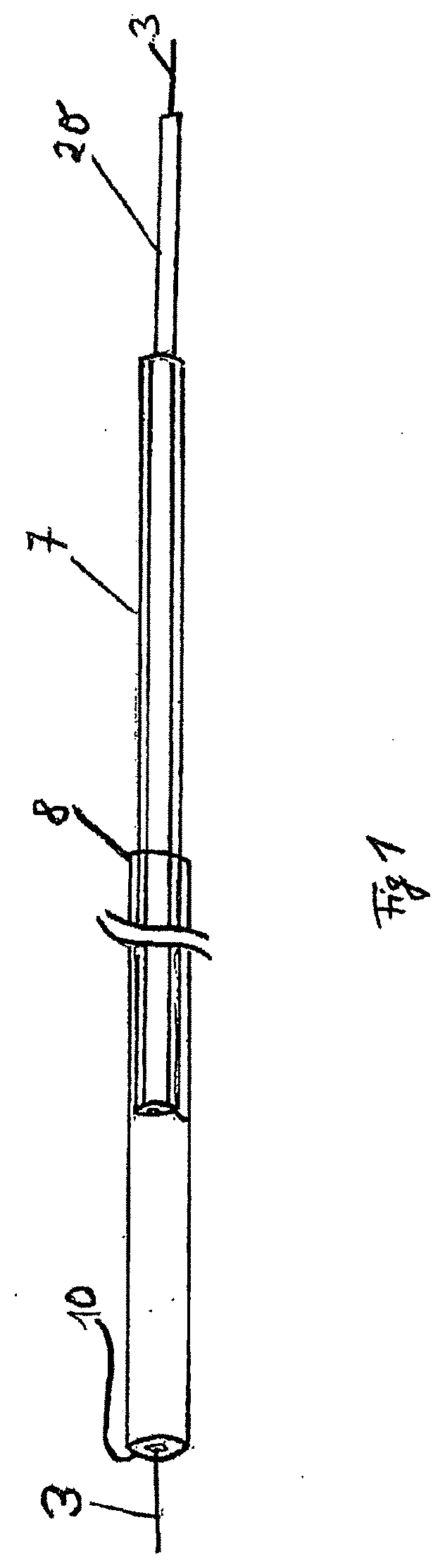
[0089]An embodiment according to the invention is shown in FIGS. 1-7. FIG. 1 is a view showing the arrangement of the complete insertion system. The compressed sponge 10, which is connected to drainage line 20, is received at the distal end of guide sleeve 8. A positioning sleeve 7 is likewise inserted into the guide sleeve via drainage line 20 and can be moved in relation to both the guide sleeve and the drainage line.

[0090]Guide wire 3 is located inside the drainage line. Said guide wire is initially placed endoscopically over a defect, and the entire insertion system can then be advanced over the wire into position. The sponge has an X-ray-proof marker, so that positioning can be carried out and monitored under X-ray surveillance.

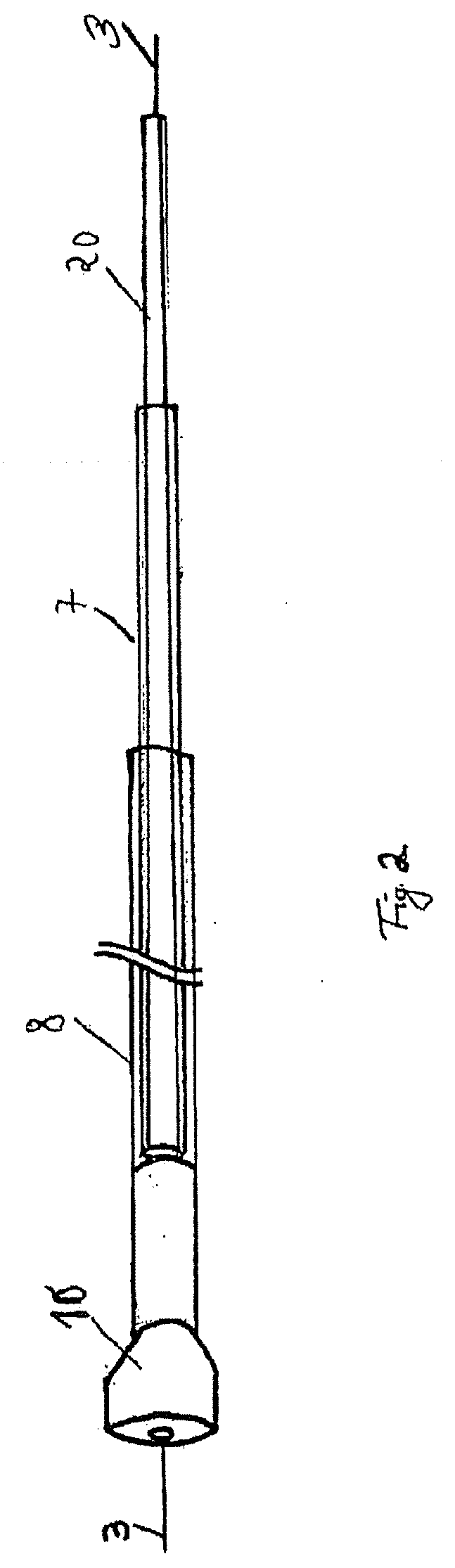
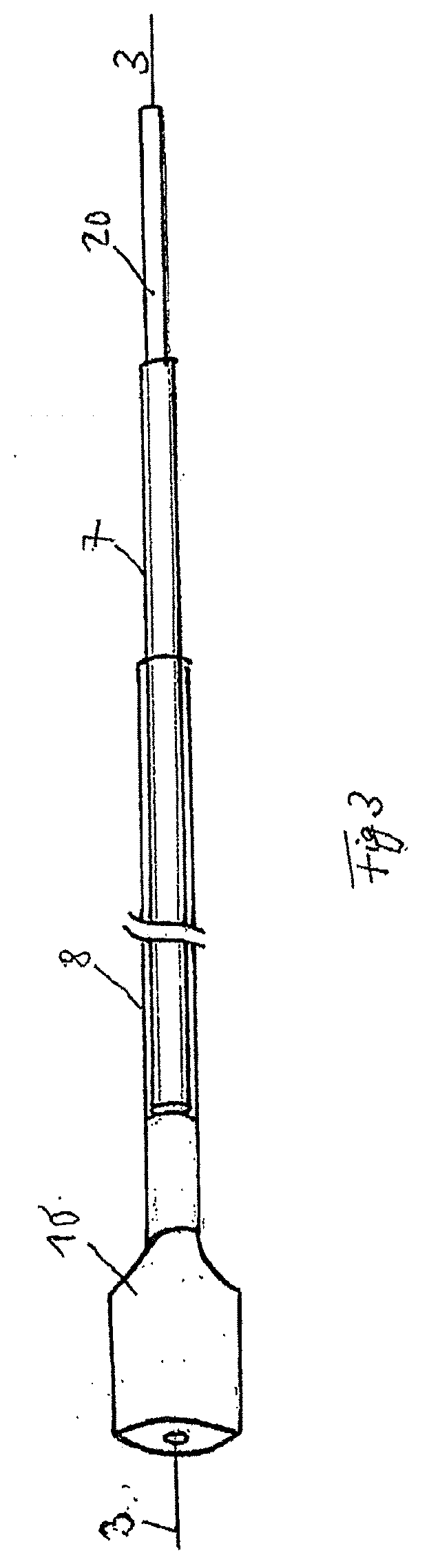
[0091]FIG. 2 shows the commencement of sponge 10 being released. Positioning sleeve 7 and guide sleeve 8 are moved towards each other, thus causing the sponge to emerge from the distal end of the guide sleeve. FIG. 3 shows continued release of the sponge...


PUM

PropertyMeasurementUnit
pressureaaaaaaaaaa
pressureaaaaaaaaaa
pressuresaaaaaaaaaa

Abstract

The invention relates to a vacuum sponge unit for use in human or animal bodies, comprising a fluid collecting member, in particular a sponge unit, and a fluid communication member, in particular a drainage tube, which is disposed at least partially in the fluid collecting member and is connected in fluidic communication to the fluid collecting member. In order to improve known devices, the inventions proposed developing the vacuum sponge unit such that the fluid collecting member has a channel for guiding a guide member, in particular a guide wire, and/or a delivery member, in particular a probe unit and/or an endoscope, through the fluid collecting member.

Description

CROSS-REFERENCE TO RELATED APPLICATIONS[0001]This application claims priority to German patent utility model 202019107105.2, filed Dec. 19, 2019. This application also claims priority to and is a Continuation in Part of U.S. patent application Ser. No. 15 / 175,283, which is a divisional of U.S. patent application Ser. No. 13 / 499,438 filed on Oct. 3, 2012, which is a U.S. National Stage of International Application Number PCT / EP2010 / 060671 filed on Jul. 22, 2010 which was published on Apr. 7, 2011 under International Publication number WO 2011 / 038949, and which claims priority to German patent application 102009043472.0 filed on Sep. 30, 2009; German patent application 102009057374.7 filed on Dec. 9, 2009; German patent application 102010013271.3 filed on Mar. 29, 2010; German patent application 102010013439.2 filed on Mar. 30, 2010, German patent application 102010013849.5 filed on Apr. 1, 2010 and German patent application 102010013848.7 filed on Apr. 1, 2010, all of which are incor...

Claims


Application Information

Patent Timeline
Patent Type & Authority Applications(United States)
IPC IPC(8): A61M1/00A61M27/00A61B90/00A61B1/00A61B1/12A61B1/273A61B17/22A61F13/36A61M25/09
CPCA61M25/09A61B1/2736A61M1/0023Y10T29/49826A61F13/36A61B2090/3966A61B17/22A61B1/12A61B1/00135A61B90/39A61M1/0088A61M2210/1021A61M27/00A61M1/0084A61M2210/1042A61B1/0008A61B1/00137A61M2210/1064A61M25/0668A61M1/84A61M1/88A61M1/90A61M1/80
Inventor LOSKE, GUNNARSCHORSCH, TOBIAS
Owner LOHMANN & RAUSCHER
Why Eureka
Try Eureka