Distortion spectrum control by space vector modulation

Active Publication Date: 2020-11-12
DR ING H C F PORSCHE AG
View PDF0 Cites 4 Cited by
  • Summary
  • Abstract
  • Description
  • Claims
  • Application Information

AI Technical Summary

Benefits of technology

The invention provides a method for controlling a power inverter that reduces distortion and improves control performance. The method involves a modulator that matches the output of the inverter to a continuous reference signal by using numerical handling of the distortion spectrum. The method also involves identifying a set of vectors in the nearest neighborhood to the reference vector, and calculating the differences between these vectors and the output vectors. These differences are then compared with a temporal profile that is shaped based on predetermined properties. The method improves the accuracy and efficiency of power conversion and reduces switching loss.

Problems solved by technology

However, the disclosed method is a binary control system that can only be used for controlling a single-phase output variable.
The possibilities of space vector modulation for controlling the multilevel systems cannot be used in this case.
However, not one of these methods is capable of controlling or regulating the distortion spectrum.
Instead, all of these methods produce marked switching harmonics in the distortion spectrum.
In the same way, norms applicable at a location of the electric vehicle (for example ISO, national standards, CISPR limit values) can lead to stipulations of spectral gaps in the distortion spectrum, which sometimes results in the predetermined properties needing to be reselected in the event of national borders being crossed, as may occur during operation of the electric vehicle.

Method used


Image

  • Distortion spectrum control by space vector modulation
  • Distortion spectrum control by space vector modulation
  • Distortion spectrum control by space vector modulation

Examples


Embodiment Construction

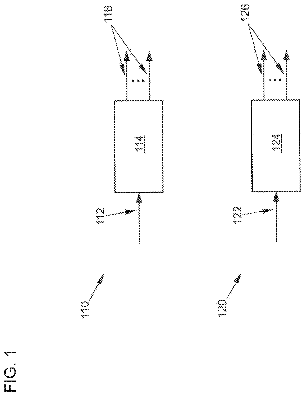
[0061]FIG. 1 uses a schematic depiction to illustrate two possible tasks of a modulator 114 and 124 controlling an inverter. First, drawing 110 depicts a modulator 114 that obtains an at least partially sinusoidal reference signal as an input signal 112, matches said reference signal to a plurality of quantized output options of the inverter by means of a space vector modulation, and the output signals 116 of said inverter consist of respectively quantized switching signals for a plurality of phases for controlling the inverter. Secondly, drawing 120 depicts an extended modulator 124 that receives an at least partially sinusoidal reference signal as an input signal 122, matches said reference signal to a plurality of quantized output options of the inverter by means of a space vector modulation, and the output signals 126 of said inverter consist of direct switching symbols for controlling the inverter.

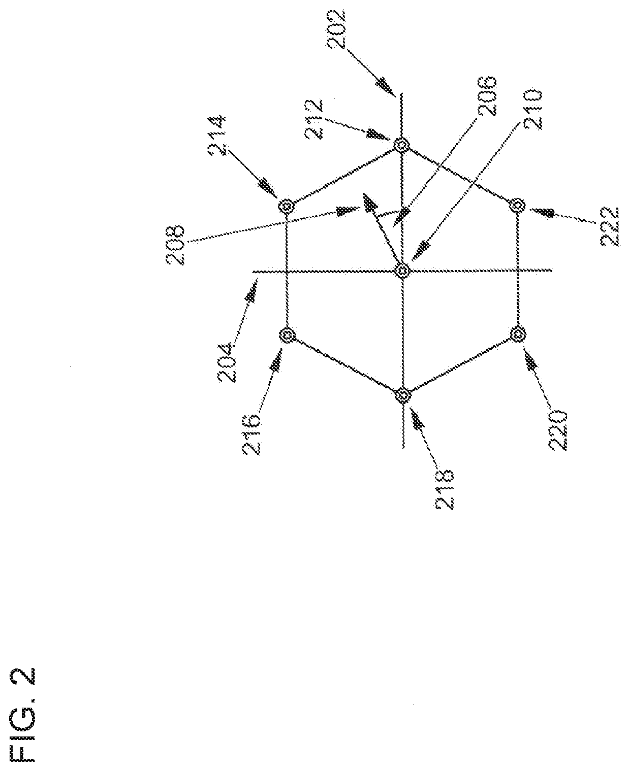
[0062]For the example of a two-level inverter, FIG. 2 shows a space vector diagra...


PUM


Abstract

The present invention relates to a method for controlling a distortion spectrum that arises for a switch-based inverter (306), which modulates at least one output variable, by virtue of space vector modulation, characterized in that different switch positions (312) causing a modulation of the at least one output variable which approximates to a predefined reference signal (310), are ascertained for each chronologically sequential switching process, a respective distortion spectrum for differences between the reference signal (310) and the at least one output variable that would arise from a respective realization of these different switch positions (312) is calculated, and the switch position (314) for which the associated distortion spectrum is most suitable according to predetermined properties is selected and implemented in the inverter (306). Further provided are a corresponding system and a corresponding modulator.

Description

BACKGROUNDField of the Invention[0001]The invention relates to a method and a system for controlling switching distortions in an inverter by means of space vector modulation, in particular when the inverter is used in an electric vehicle.Related Art[0002]In electric vehicles, an inverter and a power electronics section generally consisting of multiple semiconductor switches is used to control an electric motor. An output variable, that is to say output voltage or output current, which is modulated for the most part sinusoidally by means of the switches and also provided by the inverter in multiple phases, e.g. for the operation of a three-phase drive motor, is produced primarily by means of pulse width modulation. A large number of switching changes is necessary to model a sinusoidal shape as accurately as possible. These lead to what are known as switching harmonics, i.e. fundamentals and harmonics thereof caused by switching frequencies, in a frequency spectrum, which are manifest...

Claims


Application Information

Patent Timeline
IPC IPC(8): H02M7/5387H02M1/12
CPCH02M2007/53876H02M1/12H02M7/53871H02M1/44H02M7/483Y02B70/10H02M1/0054H02M7/53876H02M1/15H02P27/12
Inventor GOETZ, STEFANKORTE, CHRISTIAN
Owner DR ING H C F PORSCHE AG
Why Eureka
Try Eureka