
Machine tool management system

a tool management system and tool technology, applied in the field of machine tool management system, can solve the problems of system inability to determine the actual service conditions, inability to know the production information of conventional systems, fixed parts inspection cycle information and inability to be processed automatically,

Active Publication Date: 2020-11-12
FANUC LTD
View PDF1 Cites 0 Cited by
  • Summary
  • Abstract
  • Description
  • Claims
  • Application Information

AI Technical Summary

Benefits of technology

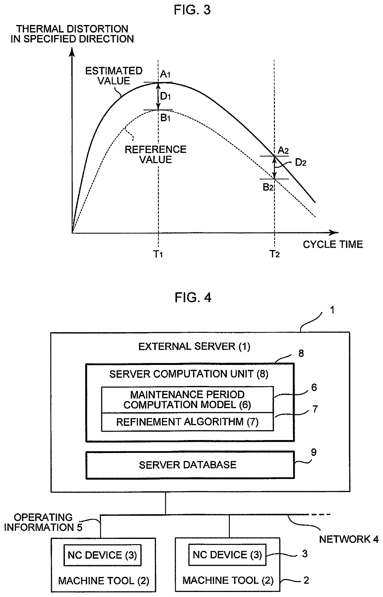
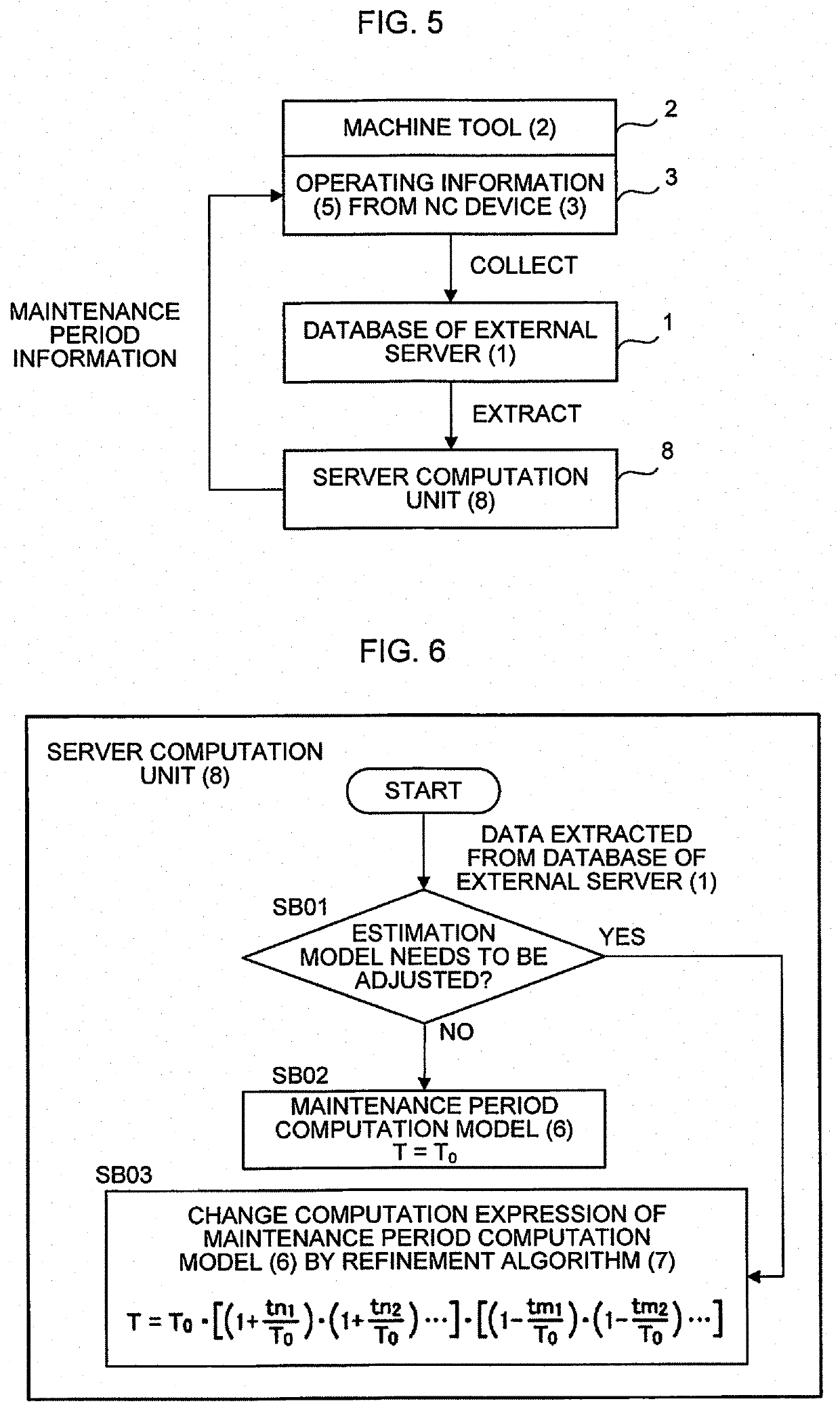
The present invention is a machine tool management system that collects and analyzes data from external sensors to determine if the tool is machining favorably. It can detect and correct thermal distortion, which can prolong the life of mechanical parts and improve maintenance effectiveness. Additionally, the system automatically refines the maintenance period model based on the machine's operating conditions, and provides advanced analyzes of actual service conditions to help improve machine tool management. Overall, the system provides an efficient and effective tool for managing machine tools.

Problems solved by technology

In the case of machining failure due to thermal distortion, however, the conventional system cannot know the production information because the system has no processing means that accurately determines the machining failure.
Moreover, in the system of the conventional arts, while the inspection schedule is calculated, inspection cycle information of the parts is fixed and cannot be processed automatically even if it needs to be changed.
Also, the system may be unable to determine the actual service conditions only by the collected signal.

Method used


Image

  • Machine tool management system
  • Machine tool management system
  • Machine tool management system

Examples


Embodiment Construction

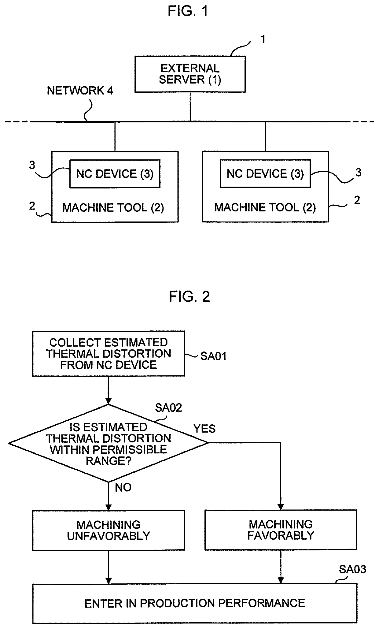
[0032]Hereinafter, embodiments of the present invention will be described in conjunction with the drawings. A description will be given to an advanced machine tool management system configured such that a server collects several kinds of data from a plurality of machine tools and analyzes the data, taking cases of collecting an estimated thermal distortion and operating information (operating data) from the machine tools and information from a sensor (data detected by the sensor) as the data to be collected from the machine tools. The management system according to the present invention involves at least one of the estimated thermal distortion, the operating information, and the information from the sensor.

[0033]FIG. 1 is a diagram showing an embodiment of the machine tool management system according to the present invention.

[0034]The machine tool management system is a system connecting an external server 1 with a large number of NC devices (numerical controllers) 3 controlling the...


PUM


Abstract

A machine tool management system connects an external server and a large number of NC devices controlling the external server and respective machine tools through a network. The system collects several kinds of signal data from the NC device of each machine tool to the external server. In the system, the external server collects an estimated thermal distortion from the NC device and compares the estimated thermal distortion with pre-stored data to determine whether the tool is machining favorably.

Description

RELATED APPLICATIONS[0001]The present application is a divisional of U.S. patent application Ser. No. 15 / 089,827, filed Apr. 4, 2016, which claims priority to Japanese Patent Application Number 2015-079771, filed Apr. 9, 2015, the disclosures of which are hereby incorporated by reference herein in their entireties.BACKGROUND OF THE INVENTION1. Field of the Invention[0002]The present invention relates to a machine tool management system.2. Description of the Related Art[0003]In a conventional machine tool management system, an external server is connected to a plurality of machine tools though a network, the server collects data from each machine tool, and the system manages the machine tools by, for example, determining operating conditions of the tools using the server.[0004]For example, Japanese Patent Laid-Open No. 2003-22107 discloses a technique in which information concerning a machining time and signal information are transferred to the external server that, and the server de...

Claims


Application Information

Patent Timeline
Patent Type & Authority Applications(United States)
IPC IPC(8): G05B19/4065H04L29/08
CPCG05B19/4065G05B2219/32422H04L67/12G05B19/042G06Q10/06G05B2219/50129G05B2219/49206G05B2219/32234
Inventor QI, XIAOGUANG
Owner FANUC LTD
Learn More