
Multi-coil electromagnetic apparatus

a multi-coil, electromagnetic technology, applied in the field of pulsed electromagnetic field, can solve the problems of difficult human compliance in sustaining the serial application of multiple treatments each requiring several minutes, the inability to adapt to specific human treatment devices, and the inability to treat certain conditions in humans and animals

Active Publication Date: 2020-11-12
AAH HOLDINGS LLC
View PDF0 Cites 0 Cited by
  • Summary
  • Abstract
  • Description
  • Claims
  • Application Information

AI Technical Summary

Benefits of technology

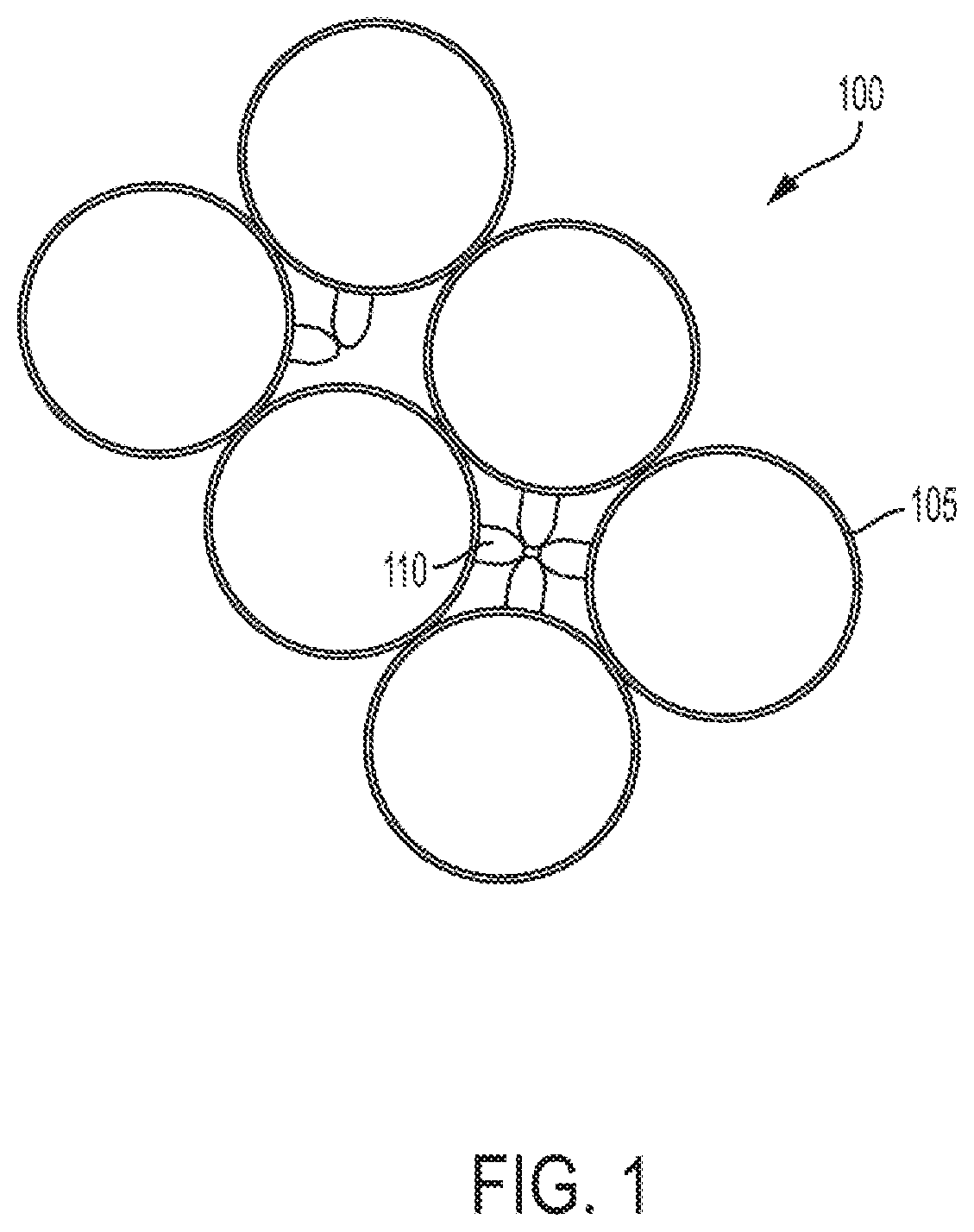
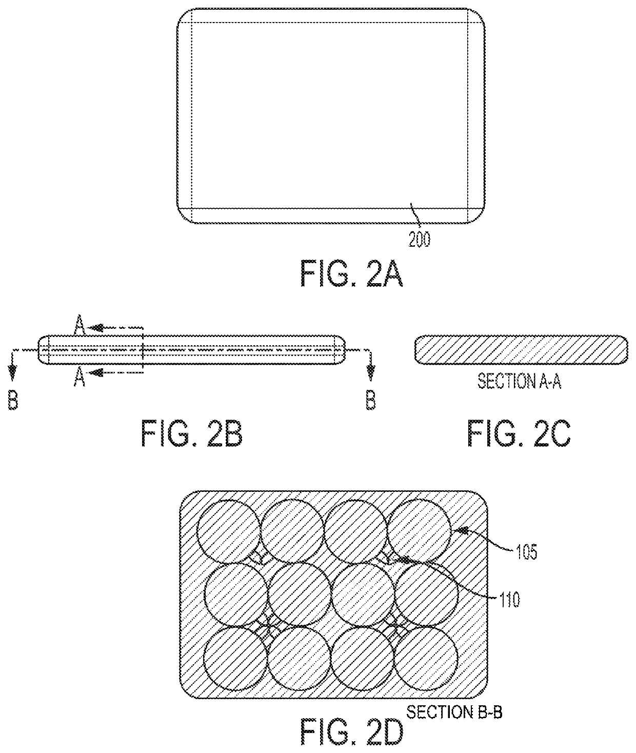
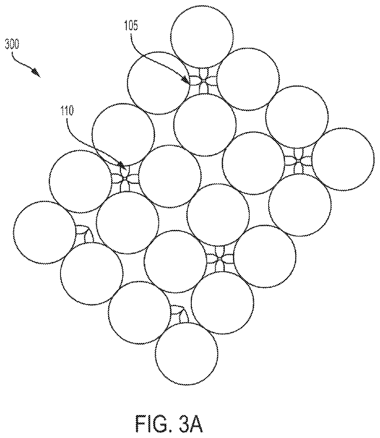
The patent describes a PEMF treatment pad or bed that can be used for human or animal patients without making them aware of the treatment. The pad or bed is comfortable for the patient and can be used for extended periods of treatment. The patent also describes a treatment pad or bed that has tracking functionality, which allows the patient to undergo extended treatment programs through multiple sessions. The invention uses an array of loop antennas with rounded indentations to generate a more consistent and therapeutically-effective treatment signal over the entire area of the pad or bed. This results in a more uniform field for PEMF signals across the treatment plane.

Problems solved by technology

However, PEMF treatment in animals presents unique challenges that are not present in the human use context.
For example, an animal patient may be reluctant to accept unusual contrivances for applying the PEMF and may resist any kind of applicator being placed proximate to the target tissue.
In addition, compliance in effecting the serial application of multiple treatments each requiring several minutes is difficult to sustain in humans or, especially, in an animal that would have to be restrained over long periods of time.
Thus, direct adaptation of specifically-targeted human treatment devices, usually employing singular or paired coils in a wearable applicator, may not be optimal for treating certain conditions in humans and animals.

Method used


Image

  • Multi-coil electromagnetic apparatus
  • Multi-coil electromagnetic apparatus
  • Multi-coil electromagnetic apparatus

Examples


example 1

[0081]FIG. 7A provides an illustration of a magnetic field on a single turn coil of wire carrying current. All the magnetic field lines have closed loops around the wire coil. Thus, one of ordinary skill in the art would understand that the magnetic field forms a three dimensional torroid. For simplicity of description, explanation on the field corresponding to a treatment signal will focus on the X, Z plane through the center of the coil.

[0082]Point “A” in FIG. 7A illustrates a point at which the magnetic field may be measured during calibration of a treatment device to thereby determine a baseline magnetic field of a wire loop in correspondence with effective magnetic fields at treatment planes of respective distances from a plane of a coil array. As reflected in FIG. 7A, a majority of the magnitude at point “A” is along the Z-axis “Az”. If a magnetic field probe were moved to Point “C” without rotating the probe off the Z-axis, it would not measure any significant magnetic field....


PUM


Abstract

A method for treating a subject by applying one or more pulsed electromagnetic field (PEMF) signals, the method including: providing an array of a plurality of loop antennas coupled to a corresponding one or more generator circuits in an enclosure configured to house at least the array of plural loop antennas, the enclosure including a treatment surface configured to be placed proximate the subject; activating one or more of the generator circuits to generate one or more preliminary treatment signals to corresponding one or more of the loop antennas; detecting a presence of the subject; and upon a condition of detecting the subject being proximate the treatment surface, activating the one or more of the generator circuits to generate another one or more treatment signals associated with the subject to the corresponding one or more loop antennas.

Description

CROSS-REFERENCE TO RELATED APPLICATION[0001]The present application is a continuation of U.S. patent application Ser. No. 15 / 972,458, filed on May 7, 2018, which claims the benefit of and priority to U.S. Provisional Patent Application No. 62 / 503,065, filed on May 8, 2017, the entire contents of each of which are incorporated by reference herein.FIELD OF THE INVENTION[0002]The present invention relates to methods and apparatuses for applying pulsed electromagnetic field (PEMF) signals in non-invasive anti-inflammatory therapy and tissue healing and growth promotion treatments in humans and animals.BACKGROUND OF THE INVENTION[0003]The application of PEMF signals has been shown to have material physiological effects on in vivo and in vitro animal tissue. As such, there has been extensive research and development in the use of weak, non-thermal electromagnetic field (“EMF”) signals for promoting wound healing and tissue growth in humans. In particular, varied apparatuses with correspon...

Claims


Application Information

Patent Timeline
Patent Type & Authority Applications(United States)
IPC IPC(8): A61N2/02A61N2/00A61B18/18G06K19/07A61N1/40
CPCA61N2/02G06K19/0723A61N1/40A61B18/18A61N2/002
Inventor RUSSO, FRANCIS J.DIMINO, ANDRE
Owner AAH HOLDINGS LLC
Learn More