
3D Printed Prosthetic Socket For Residual Limb

Pending Publication Date: 2022-08-25
ING CORP SPOL S R O
View PDF0 Cites 0 Cited by
  • Summary
  • Abstract
  • Description
  • Claims
  • Application Information

AI Technical Summary

Benefits of technology

The present invention relates to a prosthetic socket for individuals with a residual limb. The invention is made using 3D printing technology, and the structure of the socket is optimized based on various parameters such as the weight of the patient, their activity level, and the size of the prosthetic foot. By designing the distal region of the socket to be lightweight, the weight of the entire socket is reduced, increasing the comfort of the patient with the residual limb and saving material. The elastic region of the socket allows for expansion in all directions simultaneously, providing residual limb with sufficient comfort. The prosthetic socket includes a second housing that creates an air gap and is connected to the first housing in the proximal and distal region. Ribs are added for additional strength. Openings are included to remove any unused printing material during the manufacturing process. Overall, this invention provides a comfortable and lightweight prosthetic socket with improved weight distribution and reduced material usage.

Problems solved by technology

A disadvantage of these solutions is the time-consuming design and manufacture and the limitation of the design embodiment due to the technology used.
The problem of this solution is, on the one hand, the requirement for sufficient strength of the socket, and, on the other hand, the requirement to ensure comfort for the residual limb for all-day wear.
Thus, if the socket is to be strong enough to meet the strength standards imposed on sockets, such a socket is uncomfortable for the patient in case of volume changes of the limb.
A disadvantage of this solution is the absence of adaptation of the flexibility of the socket to the specific residual limb, since each portion of the residual limb includes soft tissues and bone structures differently deforming over time.

Method used


Image

  • 3D Printed Prosthetic Socket For Residual Limb
  • 3D Printed Prosthetic Socket For Residual Limb
  • 3D Printed Prosthetic Socket For Residual Limb

Examples


Embodiment Construction

[0023]Said embodiments show exemplary variants of the embodiments of the invention, which, however, have no limiting effect on the scope of protection.

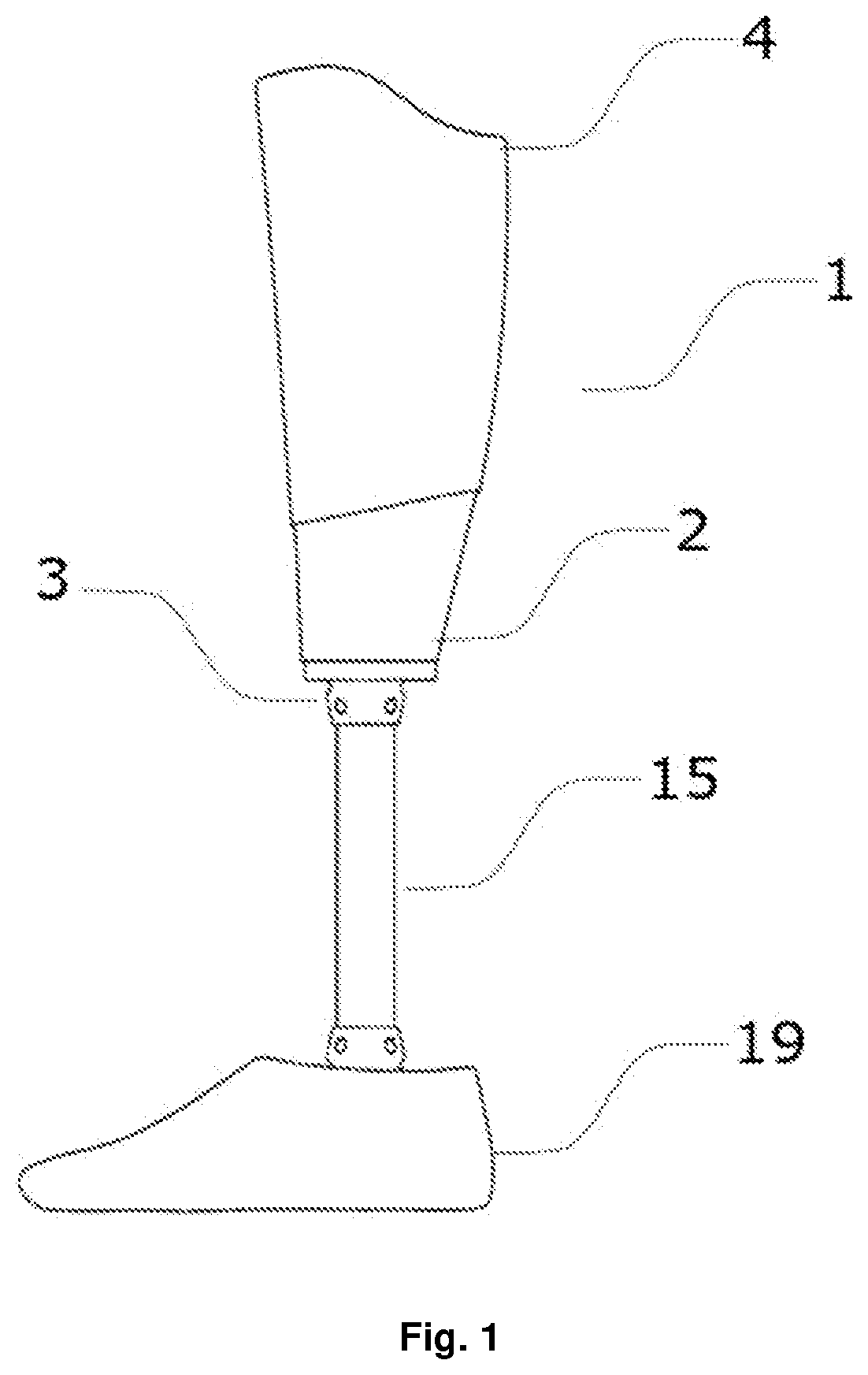
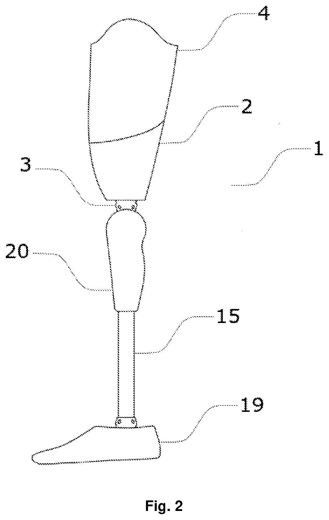
[0024]The prosthetic socket 1 according to the present invention is, as shown in FIG. 1 and FIG. 2, made of a solid material using the 3D printing technology, thereby creating a continuous and one-part shell with a cavity for the residual limb. In a preferred embodiment, the elastic module of the material used reaches 1,000 to 4,000 MPa at room temperature. Alternatively, the prosthetic socket 1 may be made by simultaneous one-part printing of several types of materials, wherein the materials may pass continuously or in leaps. In this exemplary embodiment, the elastic module of the first material is 1,000 to 4,000 MPa at room temperature and the elastic module of another material is 3 to 200 MPa at room temperature. In another exemplary embodiment, the prosthetic socket 1 is composed of several portions and thus is not made of one-par...


PUM


Abstract

The invention is a 3D printed prosthetic socket for a residual limb consisting of a 3D printed shell. The 3D printed prosthetic socket comprises a distal end adapted for linking the interconnecting adapter of the socket and a proximal end with an opening adapted for inserting the limb. The 3D printed shell comprises a first housing of the socket comprising an inner wall and an outer wall, wherein the first housing of the socket comprises a rigid region having, in the direction perpendicular to the inner wall, the rigidity of the rigid region and an elastic region having, in the direction perpendicular to the inner wall the rigidity of the elastic region. The rigidity of the elastic region is smaller than the rigidity of the rigid region, wherein the elastic region comprises a set of shaped openings and is adapted for softening the contact of the residual lower limb with the prosthetic socket, wherein the 3D printed shell is made of a single 3D printed part.

Description

TECHNICAL FIELD[0001]The invention relates to a custom-tailored 3D printed prosthetic socket for a residual limb.BACKGROUND OF THE INVENTION[0002]High-quality and well-fitting prosthetic sockets are the basis for a comfortable life of a patient with a residual limb. Due to the individual parameters of each residual limb, it is necessary to make prosthetic sockets always tailored for the specific patient. The function of the prosthetic socket is both load-bearing, wherein weight is transferred from the residual limb to the prosthesis itself, and fixating, wherein it is necessary to ensure sufficient adhesion of the socket to the limb, but at the same time the socket needs to be comfortable for the patient. Prosthetic sockets are made with respect to the condition of the residual limb, the physical activity of the patient and their weight. Since these parameters may change at shorter or longer intervals during the patient's life, it is desirable that the manufacture of the prosthetic ...

Claims


Application Information

Patent Timeline
IPC IPC(8): A61F2/80B33Y80/00A61F2/78
CPCA61F2/80B33Y80/00A61F2/7812A61F2/50A61F2002/7837A61F2/5046A61F2002/505A61F2002/5049A61F2002/6614
Inventor ROSICKÝ, JIRÍBOUMA, TOMÁSGRYGAR, ALES
Owner ING CORP SPOL S R O
Learn More