
Method and System for the 3D Design and Calibration of 2D Substrates

a technology of 2d substrates and design methods, applied in the field of systems and methods for applying 2d substrates, can solve the problems of difficult to apply this approach to more complex and irregular objects, the approach may take a long time, and the approach may not be as simpl

Inactive Publication Date: 2020-11-05
PAULSON ETHAN BRYCE +1
View PDF0 Cites 15 Cited by
  • Summary
  • Abstract
  • Description
  • Claims
  • Application Information

AI Technical Summary

Benefits of technology

This patent text is discussing a new device or system that meets certain requirements. It mentions that there are other devices or systems that can do the same things, but in a different way. The invention is providing alternative versions of these devices or systems that meet the same requirements but are just different in how they perform them. The patent also suggests that there may be other features or combinations of features that could be used instead of or in addition to the ones described here. Overall, the patent text is just mentioning different options and possibilities for the device or system described.

Problems solved by technology

For example, without limitation, automotive vinyl wraps, tattoo stencils, clothing embroidery, etc. may not be as simple as applying the 2D image to the 3D object, as warping and irregularity of the 2D image may occur.
This approach may take an extensive amount of time and results may depend on the skill of the user applying the 2D image, as well as human error.
Furthermore, it may be difficult to apply this approach to more complex and irregular objects.
Typically, this approach is limited to applying images to standard sized articles of clothing, and may not account for the fit of the article of clothing on a user.
Sections of an article of clothing before being sewed together may be used to display a 2D embroidered image upon, but in many circumstances, it may be difficult to determine the final look and fit of the product on a user without fitting the article of clothing on the user.
This may be problematic, as it requires the article of clothing to be stitched together before fitting the article of clothing to the user, so adjustments to the article of clothing or the embroidered image may only be made after stitching together the article of clothing.
With simple clothing, the cost of time to cycle between fitting and altering an article of clothing may be minimal, but with more complex clothing, the time consumed may be more substantial.
However, conventional techniques have been inadequate to perform analysis of 3D models of objects in association with each other as required for augmented reality and designing and calibrating graphics applications.
In view of the foregoing, it is clear that these traditional techniques are not perfect and leave room for more optimal approaches.

Method used


Image

  • Method and System for the 3D Design and Calibration of 2D Substrates
  • Method and System for the 3D Design and Calibration of 2D Substrates
  • Method and System for the 3D Design and Calibration of 2D Substrates

Examples


Embodiment Construction

[0028]The present invention is best understood by reference to the detailed figures and description set forth herein.

[0029]Embodiments of the invention are discussed below with reference to the Figures. However, those skilled in the art will readily appreciate that the detailed description given herein with respect to these figures is for explanatory purposes as the invention extends beyond these limited embodiments. For example, it should be appreciated that those skilled in the art will, in light of the teachings of the present invention, recognize a multiplicity of alternate and suitable approaches, depending upon the needs of the particular application, to implement the functionality of any given detail described herein, beyond the particular implementation choices in the following embodiments described and shown. That is, there are modifications and variations of the invention that are too numerous to be listed but that all fit within the scope of the invention. Also, singular ...


PUM


Abstract

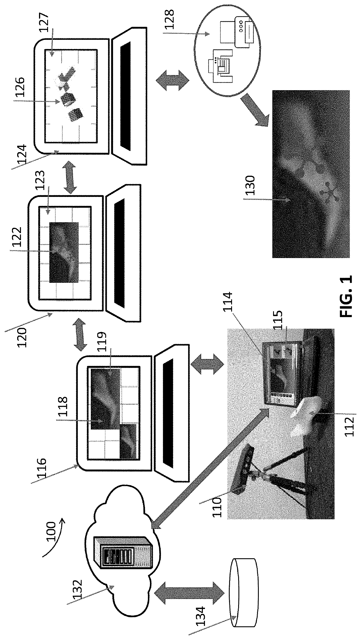
A system, program product, and method including scanning an object or entity with a three-dimensional (3D) scanning module of a computing system; providing at least one of a three-dimensional (3D) image model and a 3D mesh model from the scanned, rendered, created, or uploaded object or entity; retopologizing at least one of the three-dimensional (3D) image model and 3D mesh model; applying a UV mapping process to at least one of the retopologized three-dimensional (3D) image model and 3D mesh model, where the “U” and “V” of the UV are a two-dimensional axes of a UVW coordinate plane; projecting a two-dimensional (2D) image to at least one of the three-dimensional (3D) image model and 3D mesh model to visualize or determine if the two-dimensional (2D) image has the correct size relative to at least one of the three-dimensional (3D) image model and 3D mesh model.

Description

CROSS-REFERENCE TO RELATED APPLICATIONS[0001]The present continuation-in-part patent application claims priority benefit under 35 U.S.C. 120 of the U.S. provisional application for patent serial number 62513165 entitled “Method for providing customized and / or calibrated surface applied or fitted 2D substrates to applicable 3D objects or entities of available final 2D applications”, filed on 31 May 2017 under 35 U.S.C. 119(e) and U.S. Utility patent application Ser. No. 15 / 987,904, entitled “Method and System for the 3D Design and Calibration of 2D Substrates”, and filed on 24 May 2018 under 35 USC 111(a). The contents of these related provisional and patent applications are incorporated herein by reference for all purposes to the extent that such subject matter is not inconsistent herewith or limiting hereof.RELATED CO-PENDING U.S. PATENT APPLICATION[0002]Not applicable.FEDERALLY SPONSORED RESEARCH OR DEVELOPMENT[0003]Not applicable.REFERENCE TO SEQUENCE LISTING, A TABLE, OR A COMPU...

Claims


Application Information

Patent Timeline
Patent Type & Authority Applications(United States)
IPC IPC(8): G06T15/20G06T17/10G06T17/20G06F30/12
CPCG06F30/12G06T2219/021G06T17/20G06T15/205G06T17/10G06F2111/20G06T15/04G06T17/205G06T19/00
Inventor PAULSON, ETHAN BRYCEPAULSON, BRENT KELVIN
Owner PAULSON ETHAN BRYCE
Learn More