Drive sprocket

Active Publication Date: 2020-11-05
NEW MOTION LABS LTD
View PDF3 Cites 0 Cited by
  • Summary
  • Abstract
  • Description
  • Claims
  • Application Information

AI Technical Summary

Benefits of technology

The invention reduces stress on the sprocket during use, reducing wear and tear on the drive sprocket and friction losses, increasing transmission efficiency. The design allows for easy articulation of the drive member with each primary link rotatable about the rotational axis of each adjacent engagement pocket.

Problems solved by technology

The known drive members and known drive sprockets do not transmit power as efficiently as would be desired.
More specifically, the known drive members invariably make contact with the drive sprockets under significant loads, and in such situations, the drive members frequently tend to move relative to the teeth of the sprocket whilst maintaining contact under this high loading.
The result is that the known power transmission chains do not work efficiently on the drive sprockets.

Method used


Image

  • Drive sprocket
  • Drive sprocket
  • Drive sprocket

Examples


Embodiment Construction

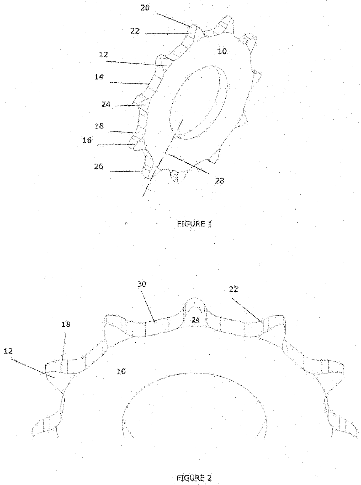
[0048]Referring initially to FIGS. 1 and 2, a drive sprocket according to an embodiment of the first aspect of invention is designated generally by the reference numeral 10.

[0049]The sprocket 10 comprises a plurality of teeth 12 that are spaced apart from one another around an outer circumference 14 of the sprocket 10.

[0050]Each tooth has a tooth profile defined by a first side 16 comprising a first engagement surface 18, and an opposite second side 20 comprising a second engagement surface 22. Each tooth further comprises a front face 24 and a back face 26, the shape of which faces being defined by the first and second sides 18, 20, which in this embodiment comprise first and second engagement surfaces. The shape of each face is symmetrical about a radial axis 28 extending along the length of each tooth.

[0051]The shape of each side 16, 20 is defined at least partially by an arc. Because each tooth 12 is symmetrical about the axis 28, the dimensions of the arcs forming all sides is ...


PUM


Abstract

A drive sprocket comprising a plurality of teeth for meshing with a drive member to transmit rotary motion, the drive member including a plurality of engagement pockets engaging the teeth of the drive sprocket, wherein each tooth has a tooth profile defined by a first side comprising a first engagement surface and an opposite second side comprising a second engagement surface, which engagement surfaces are configured such that when driven, a tooth meshes to the engagement pocket at a first contact location on the first engagement surface and also at a second contact location on the second engagement surface, wherein the first contact location is radially offset from the second contact location.

Description

CROSS-REFERENCE TO RELATED APPLICATIONS[0001]This application is a continuation-in-part (CIP) application of U.S. patent application Ser. No. 16 / 629,918, filed Jan. 9, 2020, which is a national stage application of International Patent Application No. PCT / GB2018 / 000105, filed Jul. 10, 2018, which claims priority to Great Britain Application No. 1711342.4, filed Jul. 13, 2017, Great Britain Application No. 1715782.7, filed Sep. 28, 2017, and Great Britain Application No. 1717436.8, filed Oct. 24, 2017, the disclosures of all of which are incorporated herein by reference in their entirety, including any figures, tables, and drawings.BACKGROUND TO THE INVENTION[0002]This invention relates to a drive sprocket, and particularly, but not exclusively, to a drive sprocket for use with a drive member, wherein the drive sprocket comprises a plurality of teeth. The invention also relates to a transmission system comprising a drive sprocket and a drive member, and a drive member forming part of...

Claims


Application Information

Patent Timeline
IPC IPC(8): F16G13/06B62M9/00F16H7/06
CPCB62M9/00F16G13/06F16H7/06F16G13/02F16H2007/185
Inventor PALMER, JOSH DANIELLOBMEYER, LUCASFOWLER, MARCEL
Owner NEW MOTION LABS LTD
Why Eureka
Try Eureka