Sensor device

Pending Publication Date: 2020-10-29
ROBERT BOSCH GMBH
View PDF0 Cites 0 Cited by
  • Summary
  • Abstract
  • Description
  • Claims
  • Application Information

AI Technical Summary

Benefits of technology

The present invention provides a method for accurately measuring the distance and speed of an object using infrared light. The technique allows for unambiguous measurements to be made in just one ramp duration, and prevents the need for complex frequency variation patterns. The modulation unit used in the system can generate reliable and simultaneous modulation of the light source. The scanning is performed at points in time with the same temporal distance, making the process simpler. The distance and speed of the object can be determined using a two-dimensional Fourier transform and frequency estimation. The invention provides a more efficient and reliable means to measure the distance and speed of objects.

Problems solved by technology

A short measuring time is necessary for this purpose, which, however, usually reduces the range, i.e., the distance, in which an object may be detected.
The cause thereof is that, in the case of an increasing distance, the signal-to-noise ratio for a certain distance is linearly dependent on the measuring time and, in the case of an increasing measuring time, a detection and, therefore, a measurement is then no longer possible.
As a result, an unambiguous measurement of the Doppler frequency is difficult, since a very small temporal ramp spacing and, therefore, a very short ramp duration is necessary for this purpose.

Method used


Image

  • Sensor device
  • Sensor device
  • Sensor device

Examples


Embodiment Construction

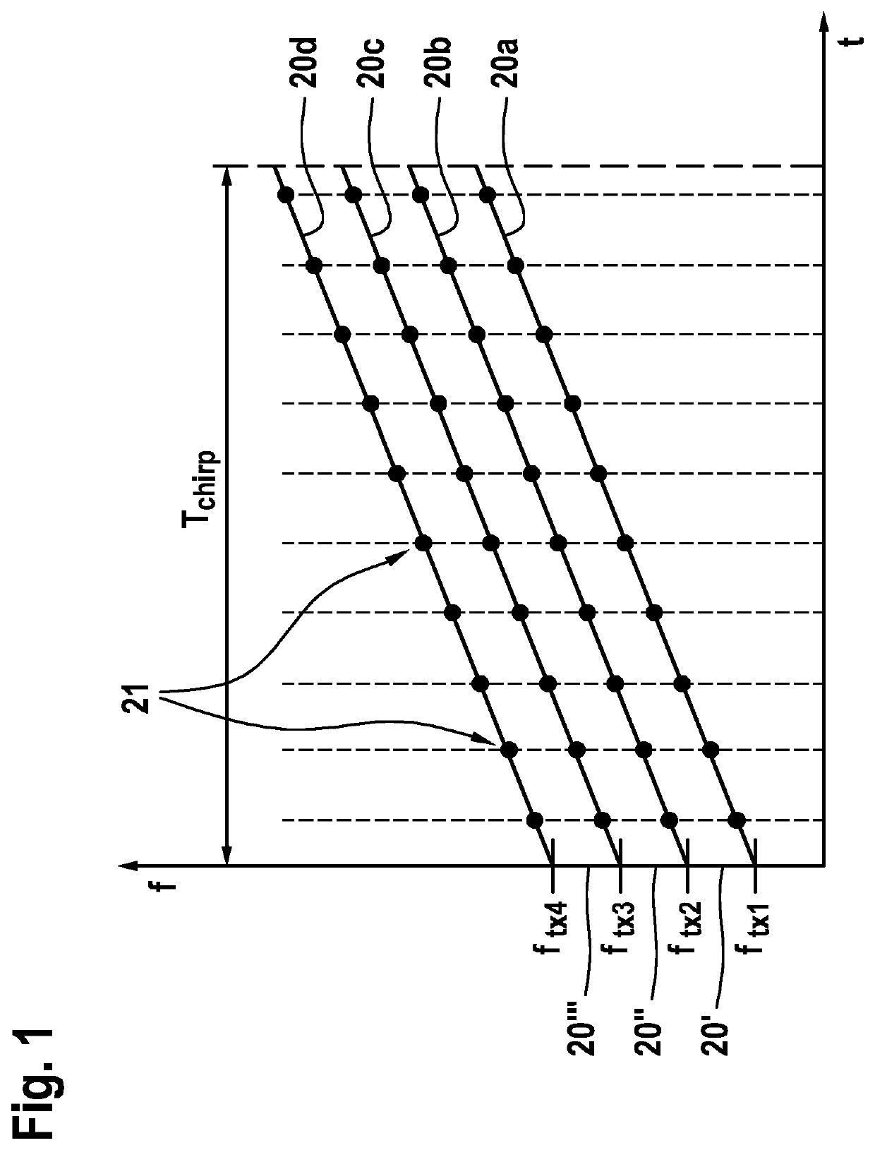
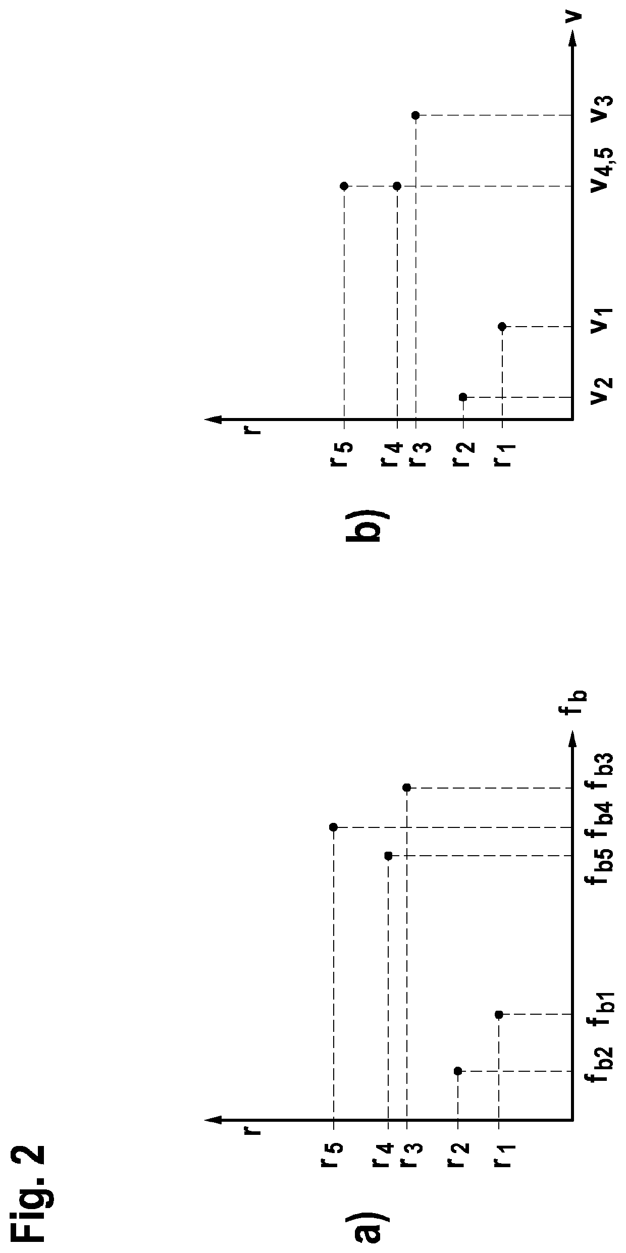
[0030]FIG. 1 shows a time-frequency representation of the temporal variation of frequencies according to a method according to one specific embodiment of the present invention, and FIGS. 2a, 2b show a two-dimensional distance-beat frequency spectrum according to a method according to one specific embodiment of the present invention.

[0031]In FIG. 1, a frequency division multiplexing, or FDM, modulation method including four simultaneously equidistantly shifted frequency ramps 20a, 20b, 20c, 20d is shown. In FIGS. 2a, 2b, a diagram for an exemplary distribution of the peaks is shown in a two-dimensional distance-beat frequency range spectrum.

[0032]In detail, FIG. 1 shows a time-frequency representation, frequency f being plotted over time t. Four frequency ramps 20a, 20b, 20c, 20d are apparent, each of which increases with the same slope in the same time interval Tchirp. Frequency ramps 20a, 20b, 20c, 20d differ with respect to their particular starting frequency by the identical freq...


PUM


Abstract

A sensor device for determining a distance and / or speed of an object, including a transmitting unit for emitting light of at least one frequency onto the object, the transmitting unit being designed for emitting light in at least one angular range, the light in the angular range being time-dependent varied essentially simultaneously with frequencies in different frequency ranges, a receiving unit for receiving light reflected by the object, the receiving unit being designed for scanning the received light in the particular frequency range at at least two points in time, and an evaluation unit, which is designed for determining the distance and / or the speed of the object on the basis of the emitted light and the points in time at which the received light was scanned.

Description

FIELD[0001]The present invention relates to a sensor device for determining a distance and / or speed of an object.[0002]Moreover, the present invention relates to a method for determining a distance and / or speed of an object.[0003]Although the present invention is usable on arbitrary transmitting units and receiving units, the present invention is described herein in conjunction with light detection and rangingLIDAR—systems.BACKGROUND INFORMATION[0004]Conventional LIDAR systems utilize narrow-band laser beams, which are deflected in a certain direction. If the laser beam strikes an object, the distance of the object may be determined on the basis of the reflection of the laser beam at the object at this angle. For this purpose, for example, a linear frequency ramp, based on the FMCW—frequency modulated continuous wave radar—principle, is emitted and, with the aid of a coherent reception, the difference frequency between the transmitted ramp and the received ramp is ascertained. On t...

Claims


Application Information

Patent Timeline
IPC IPC(8): G01S7/4915G01S7/4912G01S7/481G01S7/491G01S7/4911G01S17/34
CPCG01S7/4817G01S17/003G01S7/4915G01S7/4917G01S7/491G01S7/4911G01S17/58G01S17/34
Inventor BROSCHE, THOMASKERN, OLIVER
Owner ROBERT BOSCH GMBH
Why Eureka
Try Eureka