Device for determining the rotational speed of a transmission shaft

Inactive Publication Date: 2010-07-15
ZF FRIEDRICHSHAFEN AG
View PDF11 Cites 8 Cited by
  • Summary
  • Abstract
  • Description
  • Claims
  • Application Information

AI Technical Summary

Benefits of technology

[0007]The purpose of the present invention is to provide a device for determining the rotational speed of a transmission shaft, by means of which the speed can be determined reliably and by which the disadvantages of the prior art are eliminated or minimized.

Problems solved by technology

A disadvantage of this is that if the main shaft is wobbling, the toothed disk fixed on the main shaft also follows this wobbling motion.
However, for measurement technology reasons the toothed disk must only move within a very narrow tolerance range.
If it moves outside this tolerance range exact rotational speed measurement can no longer be guaranteed, because the teeth of the toothed disk or the gaps between them can no longer be detected reliably by the sensor.
Such a sensor, however, is substantially more expensive than a conventional rotational speed sensor with no additional evaluation electronics.
A disadvantage of this is that to position the speed sensor a long, freely suspended sensor arm is needed.
The longer such a sensor arm is, the greater is the risk that an external vibration excitation will cause the arm itself to vibrate.
Such vibration can result in an erroneous speed signal.

Method used


Image

  • Device for determining the rotational speed of a transmission shaft
  • Device for determining the rotational speed of a transmission shaft
  • Device for determining the rotational speed of a transmission shaft

Examples


Embodiment Construction

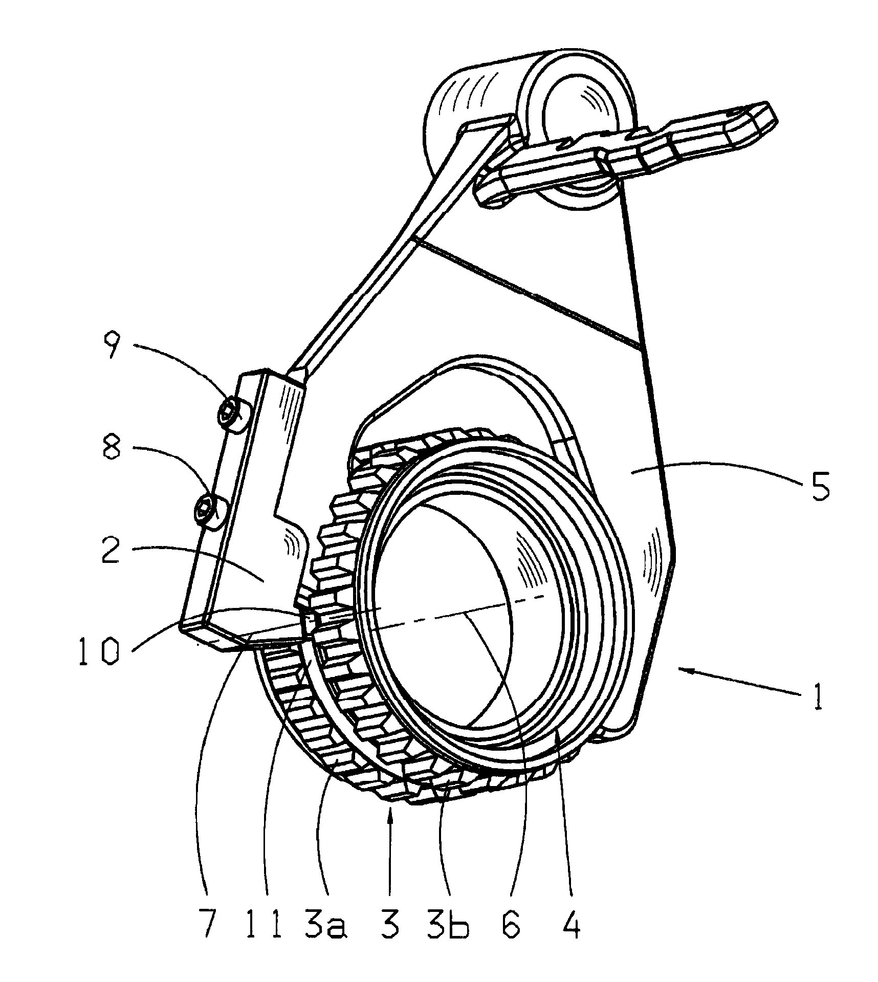
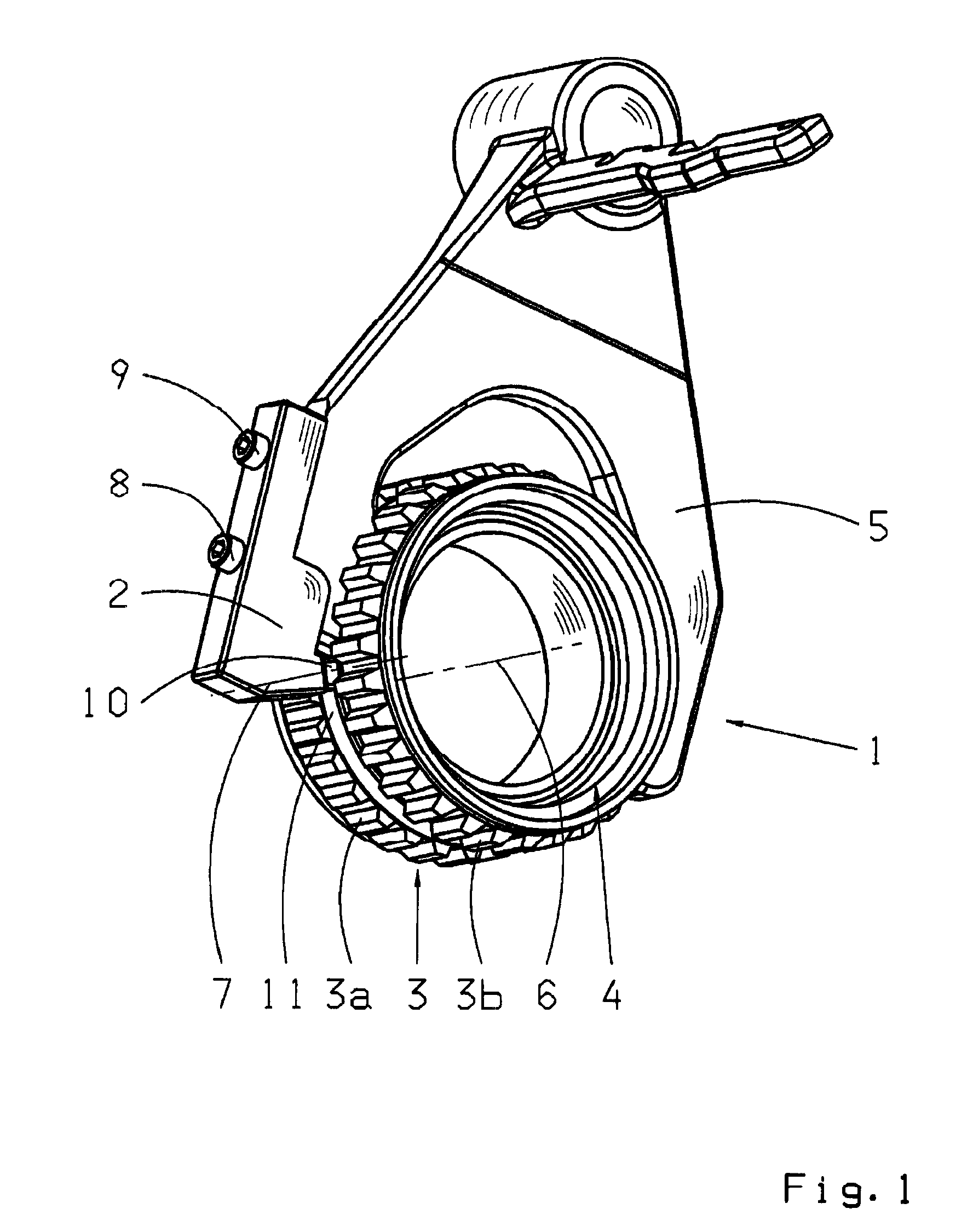
[0024]The embodiment of the device according to the invention for determining the rotational speed of a transmission shaft, illustrated in FIG. 1, comprises a speed sensor 2 and a speed indicator 3. The speed sensor 2 in this case comprises a sensor element 10 by means of which the rotational speed at the speed indicator 3 can be measured. In this embodiment the speed indicator 3 is formed by the external teeth of a sliding sleeve 4 of a clutch device 1. The speed sensor 2 is arranged on a shifting element 5, this shifting element 5 being in the form of a shift fork for actuating the sliding sleeve 4. By means of fastening elements 8, 9 the speed sensor 2 is screwed firmly to the shift fork 5. The sliding sleeve 4 has an annular groove 11 in which the shift fork 5 engages in order to actuate the sliding sleeve 4. The external teeth 3 of the sliding sleeve comprise two lateral external teeth sections 3a, 3b, between which the annular groove 11 extends.

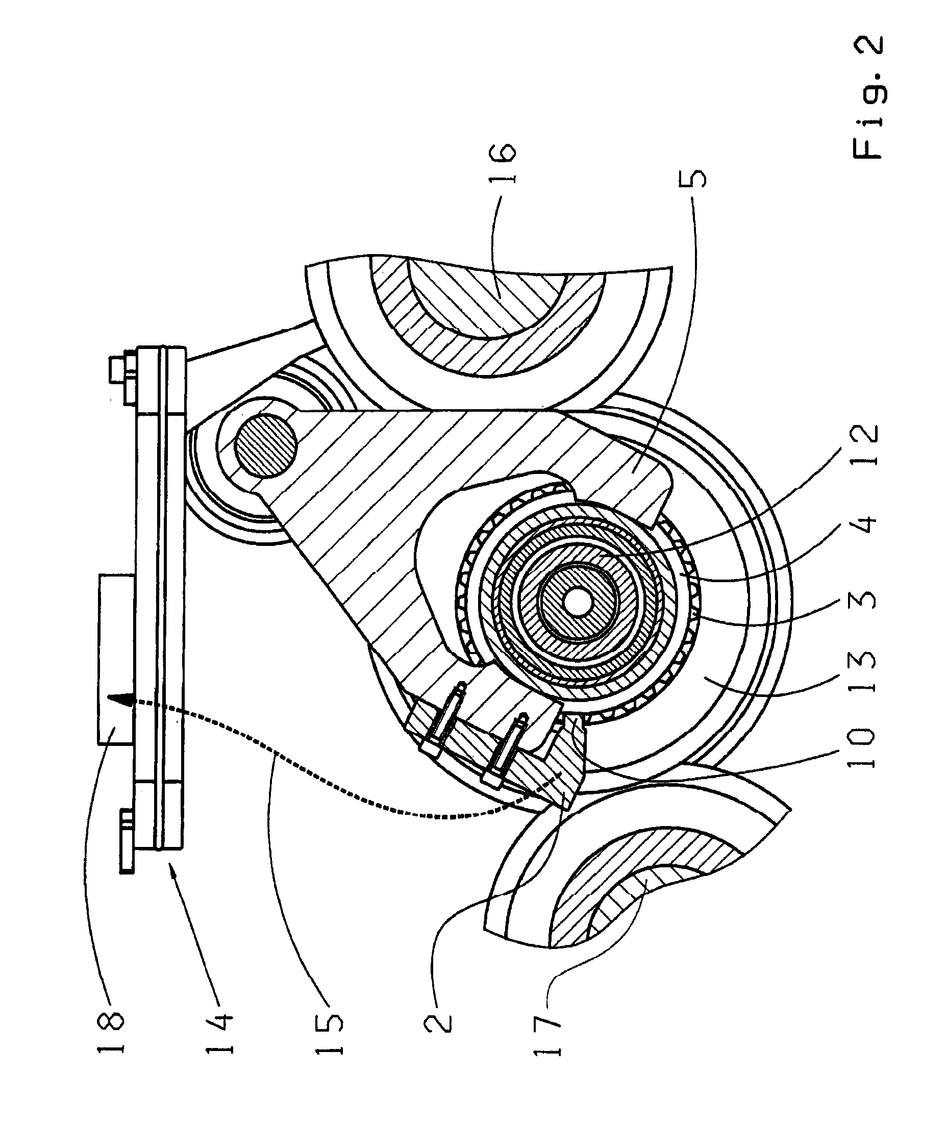
[0025]The rotational speed senso...


PUM


Abstract

The present invention concerns a device for determining the rotational speed of a transmission shaft (12), which comprises a rotational speed indicator (3) connected in a rotationally fixed manner to the transmission shaft (12) and at least one rotational speed sensor (2) comprising at least one sensor element (10), such that by means of the sensor element (10) the speed of the transmission shaft (12) can be detected at the speed indicator (3). According to the invention, the speed sensor (2) is attached to a shifting element (5) for actuating a sliding sleeve (4) of a clutch device (1) that is connected axially movably but in a rotationally fixed manner to the transmission shaft (12).

Description

[0001]This application is a National Stage completion of PCT / EP2008 / 056459 filed May 27, 2008, which claims priority from German patent application serial no. 10 2007 025 666.5 filed Jun. 1, 2007.FIELD OF THE INVENTION[0002]The present invention concerns a device for determining the rotational speed of a transmission shaft. Moreover the invention concerns a transmission, in particular for a motor vehicle, with such a device.BACKGROUND OF THE INVENTION[0003]From the prior art, transmissions are known, which comprise rotational speed detection devices for generating a speed signal, for a motor vehicle. These rotational speed detection devices comprise in essence a signal emitter or speed indicator connected rotationally fixed to a corresponding transmission shaft, this being associated with a fixed speed sensor in order to measure the rotational speed from the speed indicator.[0004]In known motor vehicle transmissions with two countershafts, a main shaft is mounted with sufficient pla...

Claims


Application Information

Patent Timeline
IPC IPC(8): G01P3/44
CPCF16H59/38G01P3/44F16H63/32
Inventor FUHRER, KIM
Owner ZF FRIEDRICHSHAFEN AG
Why Eureka
Try Eureka