Brake pad for a disk brake assembly, comprising a suction groove in a front region and a chamfered front region

a technology of disk brakes and brake pads, which is applied in the field of brake pads for disk brake assemblies, can solve the problems of increasing the area of the friction surface disposed between the collection groove and the front edge, and achieves the effect of optimizing the run, retaining the collection efficiency of braking particles, and wearing more quickly

Active Publication Date: 2020-10-29
TALLANO TECH
View PDF0 Cites 3 Cited by
  • Summary
  • Abstract
  • Description
  • Claims
  • Application Information

AI Technical Summary

Benefits of technology

[0017]Thus, the chamfered portion of the front region allows the braking function to be optimally run in. Moreover, braking particle capture is all the more efficient the closer the collection groove is to the rear edge and the larger an area of a friction surface disposed between the collection groove and the front edge. Moreover, the presence of the chamfered portion on the front region allows the center of mass of the lining to be moved towards the front region. Thus, when a pressure is exerted on the plate supporting the lining to impose contact between the lining and the disk, the front region will become worn more quickly, which will result in an in...

Problems solved by technology

Thus, when a pressure is exerted on the plate supporting the lining to impose contact between the lining and the disk, the front region will become worn more quickly, which will result in an inc...

Method used


Image

  • Brake pad for a disk brake assembly, comprising a suction groove in a front region and a chamfered front region
  • Brake pad for a disk brake assembly, comprising a suction groove in a front region and a chamfered front region
  • Brake pad for a disk brake assembly, comprising a suction groove in a front region and a chamfered front region

Examples


Embodiment Construction

[0038]It should be noted that, for clarity purposes, only elements beneficial for understanding the embodiments described have been shown and will be described.

[0039]Moreover, unless specified otherwise, the expressions “substantially” and “about”, etc. mean that a slight variation from the nominal value considered is possible, in particular of a low percentage, in particular to the nearest 10%.

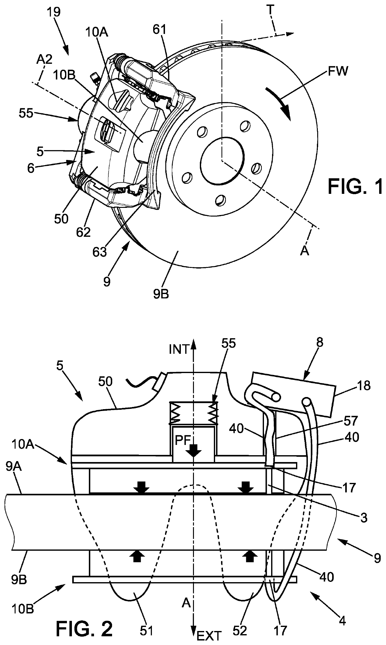
[0040]FIGS. 1 and 2 show a disk brake system 19 according to the invention for a vehicle. In this embodiment, the vehicle is a motor vehicle, in this case a light vehicle. It should however be noted that the invention can be implemented for any type of vehicle, such as a tractor for a semi-trailer, a bus or an agricultural tractor, or for any type of railway rolling stock, such as a locomotive or a railway car.

[0041]The disk brake system 19 according to the invention includes a disk 9 of axis A, integral with a wheel of the vehicle. The disk 9 has a side face 9A and an opposite side face 9B. ...


PUM


Abstract

The brake pad (10A, 10B) comprises a lining (22) made of friction material and a plate (20) supporting the lining (22). The lining (22) comprises: —a rear edge (34) located on the side where the disk (9) is able to come out of an interface with the pad (10A, 10B) when the disk (9) rotates in an direction of travel of the vehicle, and a front edge (36); —a collection groove (3) that opens into the friction face (30) and is located close to the rear edge (34). The lining (22) has a rear region (60) comprising the rear edge (34) and the collection groove (3), and a front region (62) comprising the front edge (36), the front region (62) having a chamfered portion (66) such that an area of a friction surface of the front region (62) increases when a thickness of the front region (62) decreases.

Description

FIELD OF THE INVENTION[0001]The present invention relates to vehicles, in particular motor vehicles and also to railway rolling stock. More specifically, the invention relates to the braking of vehicles and of railway rolling stock. The invention further relates to the brake pads for disk brake assemblies for these vehicles and these railway rolling stock.[0002]It should be noted that, according to the invention, the vehicle can be of any type and can in particular be a car, a lorry or a bus. Similarly, the railway rolling stock can be a train, a tramway or even a metro.BACKGROUND OF THE INVENTION[0003]A vehicle or a railway rolling stock generally comprises a braking system. The braking system can in particular be a disk brake system. The braking system thus includes a disk, integral with a wheel or with an axle of the vehicle or of the railway rolling stock. Thus, when the wheel, or the axle, is set in rotation to allow the vehicle or the railway rolling stock to move, the disk is...

Claims


Application Information

Patent Timeline
IPC IPC(8): F16D65/00F16D65/092F16D69/00F16D55/22B60T1/06
CPCF16D65/0031B60T1/065F16D69/00F16D2069/004F16D65/092F16D55/22
Inventor ADAMCZAK, LOÏCMAISTRE, ADRIEN
Owner TALLANO TECH
Why Eureka
Try Eureka