
System and method for gas turbine engine control

a technology for gas turbine engines and systems, applied in the field of gas turbines, can solve problems such as inability to model gas turbine engines, under-500 kgf thrust, and inability to operate smoothly

Inactive Publication Date: 2020-10-29
VIETTEL GRP
View PDF9 Cites 2 Cited by
  • Summary
  • Abstract
  • Description
  • Claims
  • Application Information

AI Technical Summary

Benefits of technology

The invention proposes a method to create a model for a gas turbine with nonlinear control characteristics using piecewise linear approximation of nonlinear functions. By dividing the operational range of the engine into smaller ranges and modeling the engine's operational characteristic in these ranges, a smooth operation of the engine can be achieved even when the control parameters change. The technical effect of this invention is to create a reliable and efficient control system for gas turbines.

Problems solved by technology

In some gas turbines where the simplicity, compactness and affordability are the highest priorities, gas turbine with thrust under 500 kgf for small aircraft, for example, the alternator, the rectifying circuit and the FCU may become inappropriate.
These algorithms are not based on modeling of the gas turbine, and we cannot use them to simulate the operation of the engine.
For example, the Ziegler-Nichols and related algorithms may not always work well for systems with significant dead-time, and can be too aggressive for some systems.
In another example, the Cohen-Coon and similar algorithms may not always work well for systems which are modeled by integrators, such as unloaded turbines.

Method used


Image

  • System and method for gas turbine engine control
  • System and method for gas turbine engine control
  • System and method for gas turbine engine control

Examples


Embodiment Construction

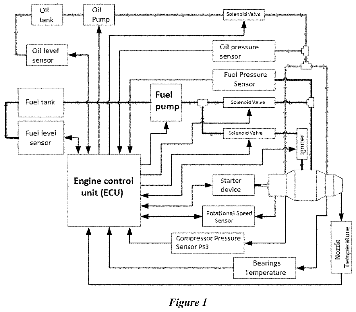
[0014]The System and Method for gas turbine engine control proposed by this invention will now be explained in details. The control system consists of following components:[0015]System of sensors, including: thermocouple type temperature sensors, resistive pressure sensors, rotational speed sensor, oil level sensor and fuel level sensor. Rotational speed sensor can be of type inductive proximity or fiber-optic. Signal from the sensor is processed by an op-amp precision rectifier circuit to filter out noise. The output signal is square wave form and reflects accurately the time it takes the turbine blades to pass through the sensor, thus helping the ECU calculate the instantaneous rotational speed.[0016]System of actuators, including: solenoid valves that open and close the fuel supply and lubricating oil line, fuel pump and oil pump driven by electric motors, ignition device, starter device (pneumatic valve to open and close compressed air, or electric starter motor, or Pyro-starter...


PUM


Abstract

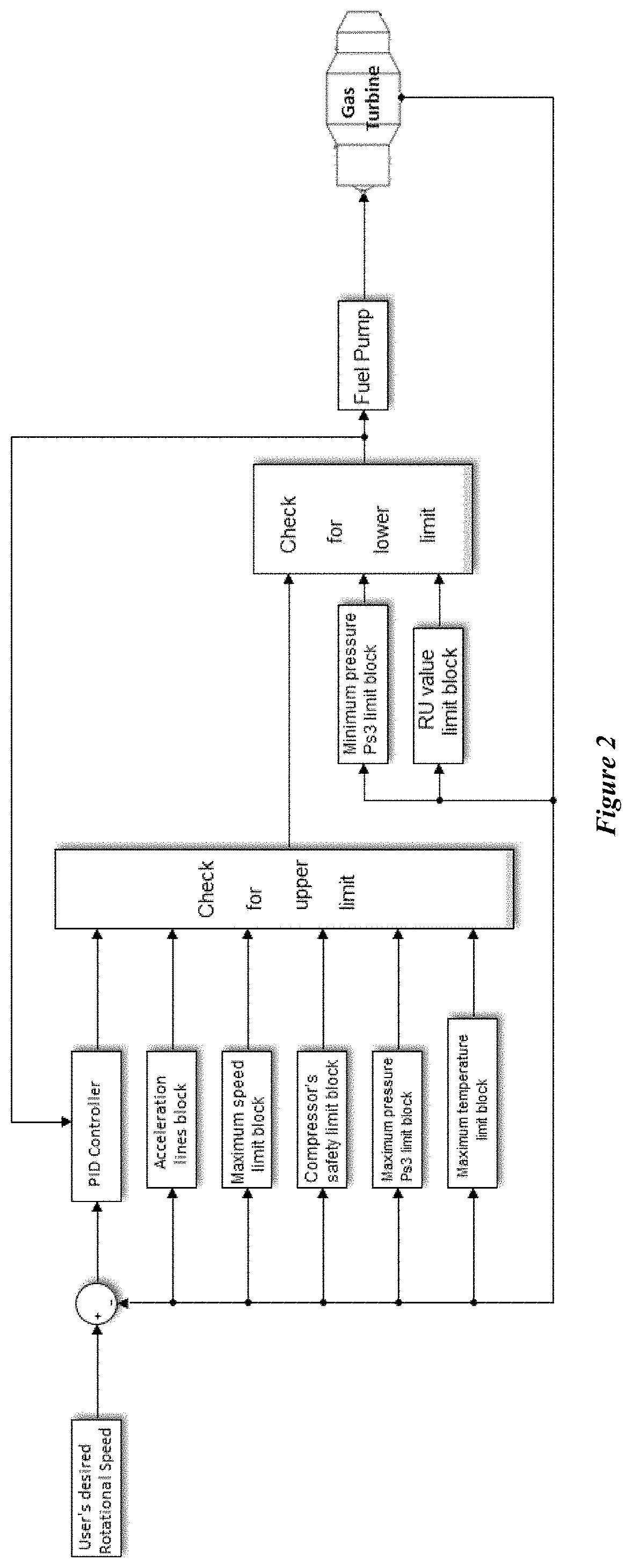
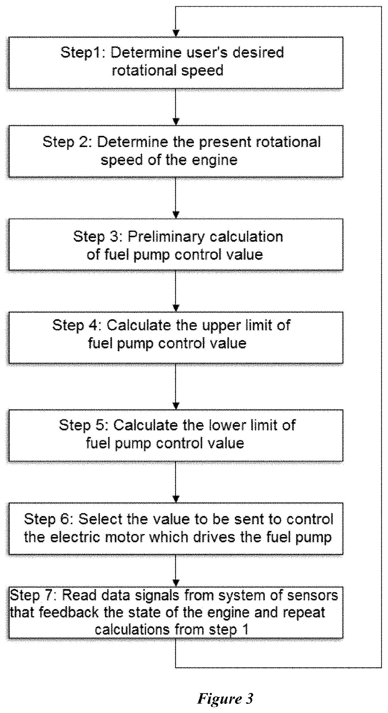
A system and method for controlling gas turbine engines with maximum thrust of less than 500 kgf. The control system includes electronic control unit (“ECU”), sensors and actuators. To ensure the requirement of compactness, physical control system simplicity but maintain stability and accurate operation for the engine, the control system does not include components such as Fuel Control Unit (“FCU”), alternator and corresponding rectifier circuits. A sensor, instead of alternator's wave form signal, is used to detect the rotational speed of the engine. Voltage regulation into the electric motor driving the fuel pump controls fuel flow, instead of the FCU. The control method consists of upper and lower limits computation calculation blocks of the control signal, and PID control algorithm block with coefficients designed to be suitable for the engine operating ranges. Control is implemented through a 7-step calculation process. Piecewise linearization modeling and tuning PID coefficients is also presented.

Description

FIELD OF THE INVENTION[0001]This invention refers to the field of gas turbines. Specifically, it proposes a system and method to control gas turbines. The scope of this invention is aviation jet engines with a maximum of thrust less than 500 kgf.DESCRIPTION OF THE RELATED ART[0002]In an aircraft gas turbine, as taught by U.S. Pat. No. 4,716,531, for example, the electronic control unit (hereinafter referred to as “ECU”) determines a command value and sends the same to a fuel control unit (hereinafter referred to as “FCU”) interposed in a Fuel Supply System that pumps fuel from a fuel tank and Supplies it to a fuel nozzle installed in a combustion chamber of the engine. An alternator is integrated in the engine and the rotational speed is detected based on the wave form generated by the alternator. A specific circuit rectifies the current from the alternator so that the microcomputer can read the output wave form. The electricity created by the alternator also serves other equipment ...

Claims


Application Information

Patent Timeline
IPC IPC(8): F02C9/28
CPCF05D2260/80F02C9/28
Inventor NGUYEN, PHI MINHBUI, VAN SONNGUYEN, HUY HOANGPHAM, VAN SONTRINH, THANH NAM
Owner VIETTEL GRP
Learn More