
Method for producing an insulation panel

Inactive Publication Date: 2020-10-22
HENNECKE
View PDF0 Cites 1 Cited by
  • Summary
  • Abstract
  • Description
  • Claims
  • Application Information

AI Technical Summary

Benefits of technology

The present invention aims to develop a process that can apply reaction mixture to a continuously moving surface layer evenly, preventing caking on the distributor walls and ensuring an even age distribution of the reactive mixture on the different strands to avoid coalescence and physical property issues. The invention also seeks to minimize bubble impact when applying the reactive mixture to the cover sheet.

Problems solved by technology

This results in a chaotic and unfavorable cell orientation in the confluence zones.

Method used


Image

  • Method for producing an insulation panel
  • Method for producing an insulation panel
  • Method for producing an insulation panel

Examples


Embodiment Construction

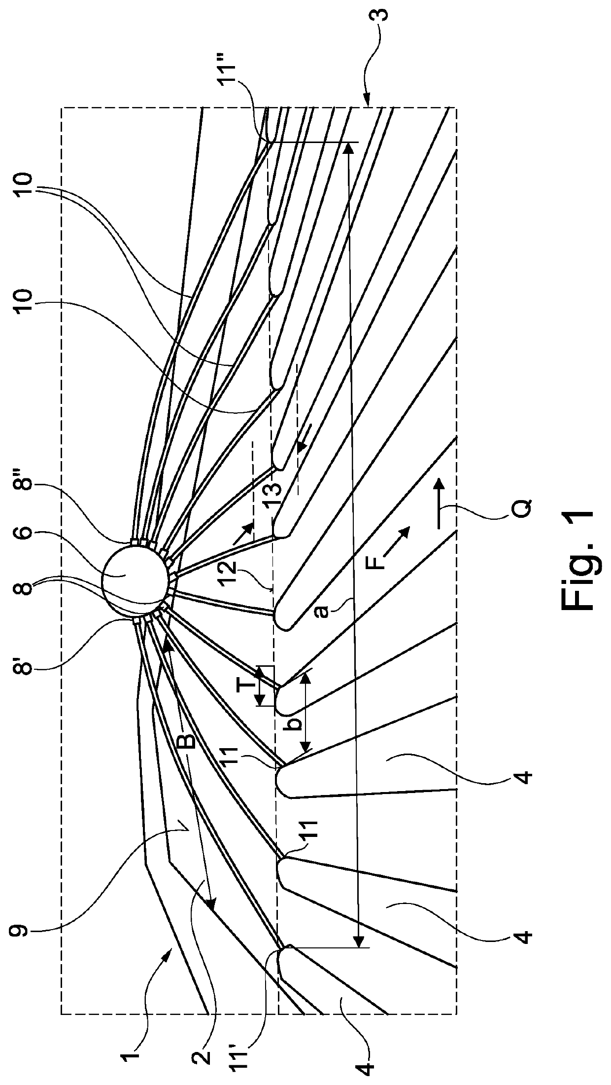
[0036]FIG. 1 shows schematically an installation used to produce an insulating panel 1 (insulating panel as a foam composite element) by applying a layer of insulating material 3 in the form of a polyurethane reactive mixture 4 to a cover layer 2. The insulating panel 1 has a width B.

[0037]Here, the cover layer 2 moves below a stationary distributor 6, from which the reactive mixture 4 is discharged, in a conveying direction F at constant speed.

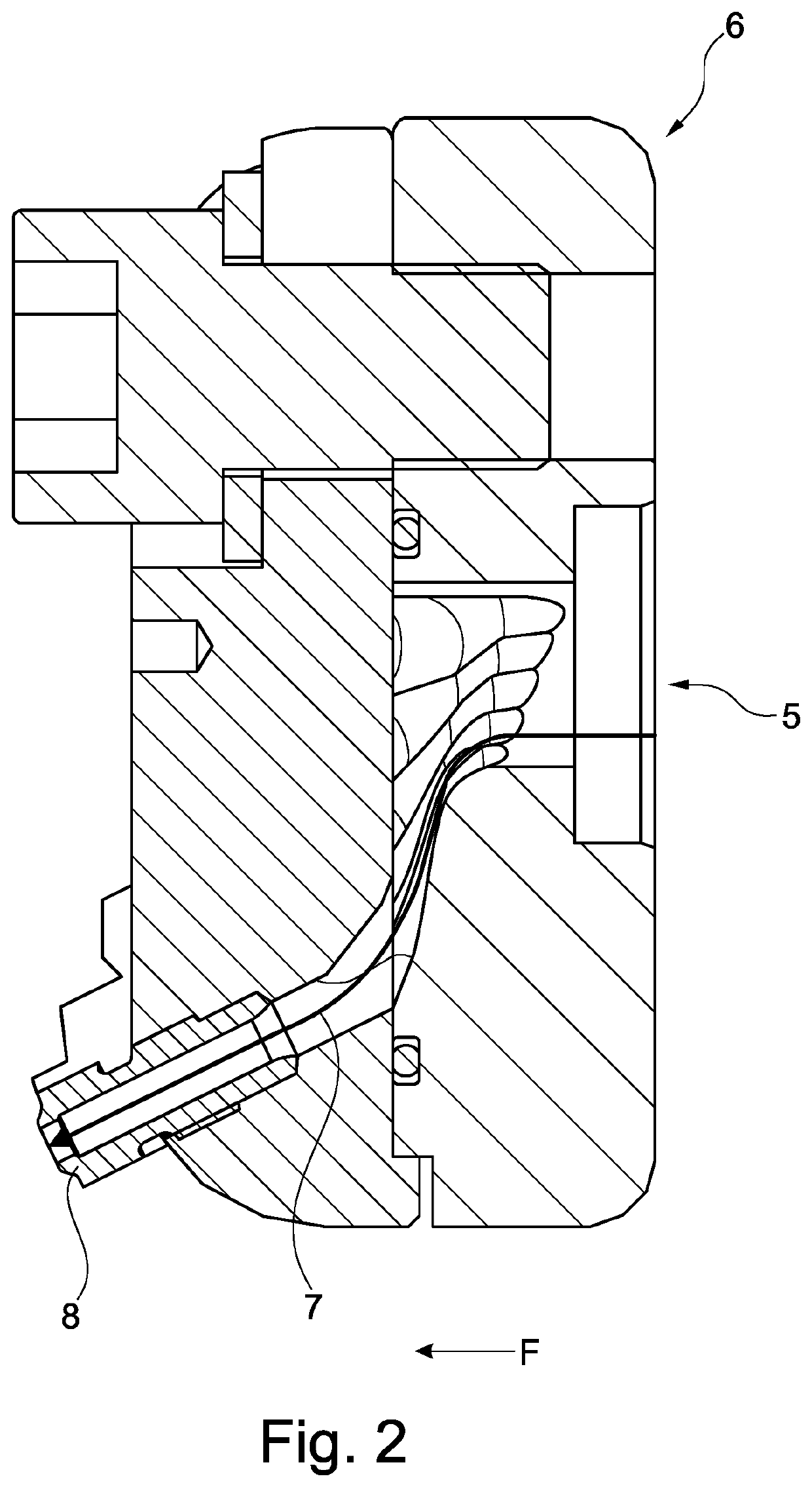
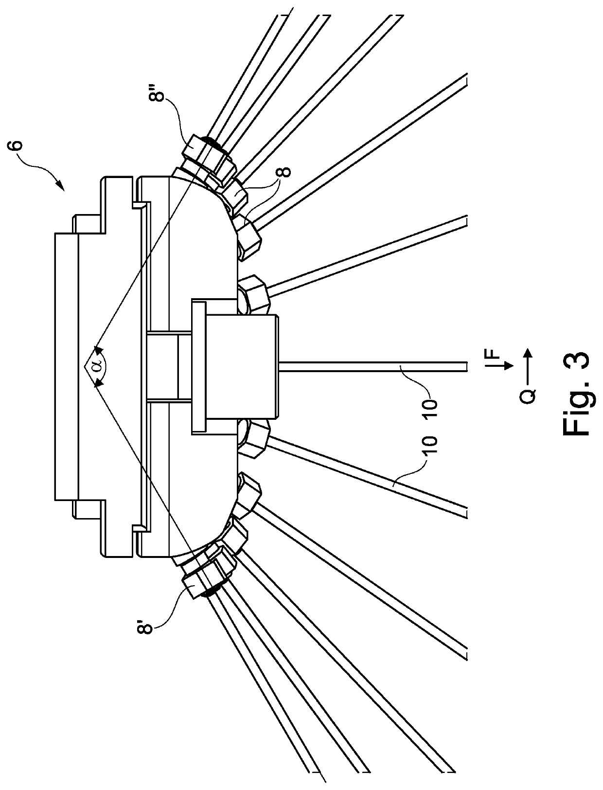
[0038]As can be seen in synopsis with the other figures, the polyurethane reactive mixture 4 is discharged from the distributor 6 in the form of a number of jets 10, i.e. the reactive mixture 4 is ejected through nozzle openings 8 in the distributor 6 so that it reaches the cover layer 2 as a free jet following the shape of a flight parabola, as can best be seen in FIG. 1, where it contacts the upper side 9 of the cover layer 2 at a corresponding number of impact points 11.

[0039]In the shown embodiment, eleven jets 10 are provided, whereby th...


PUM

PropertyMeasurementUnit
Lengthaaaaaaaaaa
Lengthaaaaaaaaaa
Lengthaaaaaaaaaa

Abstract

A method for producing an insulation panel, including a cover layer and a layer of insulating material located thereon, between which the layer of insulating material is located. The insulating material is produced by metering at least two components of a reactive mixture, mixing and feeding them to an inlet of a distributor. The reactive mixture is guided in the distributor along a flow path to at least five nozzle openings and discharged. The reactive mixture is applied from each nozzle opening in a free jet onto the upper side of the cover layer which moves in a conveying direction relative to the distributor. The impact points of the jet of reactive mixture on the cover layer lie substantially on a line which extends transversely to the conveying direction. The distance of the two laterally outermost impact points is at least 70% of the width.

Description

CROSS-REFERENCE TO RELATED APPLICATIONS[0001]The present application claims priority of DE 10 2019 110 091.7, filed Apr. 17, 2019, the priority of this application is hereby claimed and this application is incorporated herein by reference.BACKGROUND OF THE INVENTION[0002]The invention relates to a method for producing an insulation panel of predetermined width, comprising at least one cover layer and a layer of insulating material (especially insulating foam) located thereon, preferably comprising two cover layers, between which the layer of insulating material is located, wherein the insulating material is produced by metering at least two components of a reactive mixture, mixing the same and feeding them to an inlet of a distributor, wherein the reactive mixture being guided in the distributor along a flow path to a number of nozzle openings and being discharged via the nozzle openings, wherein the reactive mixture being applied to the upper side of the at least one cover layer wh...

Claims


Application Information

Patent Timeline
IPC IPC(8): B05B7/00B05B7/26B05B13/02
CPCB05B7/26B05B7/0018B05B13/0221B05B1/14B05B7/0012B05B7/04B29C44/32B29C44/367B29C44/461B29C44/50B29K2075/00F16L59/028F16L59/029B29C44/28B29C44/46B29C44/468B29K2875/00B29L2009/003B29L2031/776
Inventor SCHAMBERG, MARTINSTEEN, ALEXANDER
Owner HENNECKE
Learn More