Control system for internal combustion engine, and internal combustion engine

a control system and internal combustion engine technology, applied in the direction of electric control, machines/engines, fuel injecting pumps, etc., can solve the problems of insufficient swing-back amount, inability to accurately estimate the crank angle at the time of engine stoppage, etc., to achieve the effect of increasing the volume of the fuel chamber and decreasing the amoun

Active Publication Date: 2020-10-15
TOYOTA JIDOSHA KK
View PDF0 Cites 0 Cited by
  • Summary
  • Abstract
  • Description
  • Claims
  • Application Information

AI Technical Summary

Benefits of technology

The patent text describes a control system for an internal combustion engine that uses a high pressure fuel pump and in-cylinder fuel injection valve. The controller calculates the number of driving times of the high pressure fuel pump by using a stop-time counter value and a crank counter value. The stop-time counter value is calculated based on the value of the crank counter when the engine is stopped. The controller also corrects the swing-back amount used for calculating the stop-time counter value based on the difference between the number of driving times calculated using the stop-time counter value and the number of driving times calculated based on the high pressure system fuel pressure. This allows for accurate control of the engine without excessive correction. The technical effect of this control system is improved engine performance and efficiency.

Problems solved by technology

In addition, not only in the case of being estimated by the method of calculating the swing-back amount based on the reverse flow amount of the air, but also in the case where the estimated swing-back amount has the deviation from the actual swing-back amount, the crank angle at the time when the engine is stopped cannot be correctly estimated and control at the time when the engine is started can be adversely affected.
When the number of driving times calculated based on the stop-time counter value and the value of the crank counter is more than the number of driving times calculated based on the high pressure system fuel pressure, the estimated swing-back amount may have been too large.

Method used


Image

  • Control system for internal combustion engine, and internal combustion engine
  • Control system for internal combustion engine, and internal combustion engine
  • Control system for internal combustion engine, and internal combustion engine

Examples


Embodiment Construction

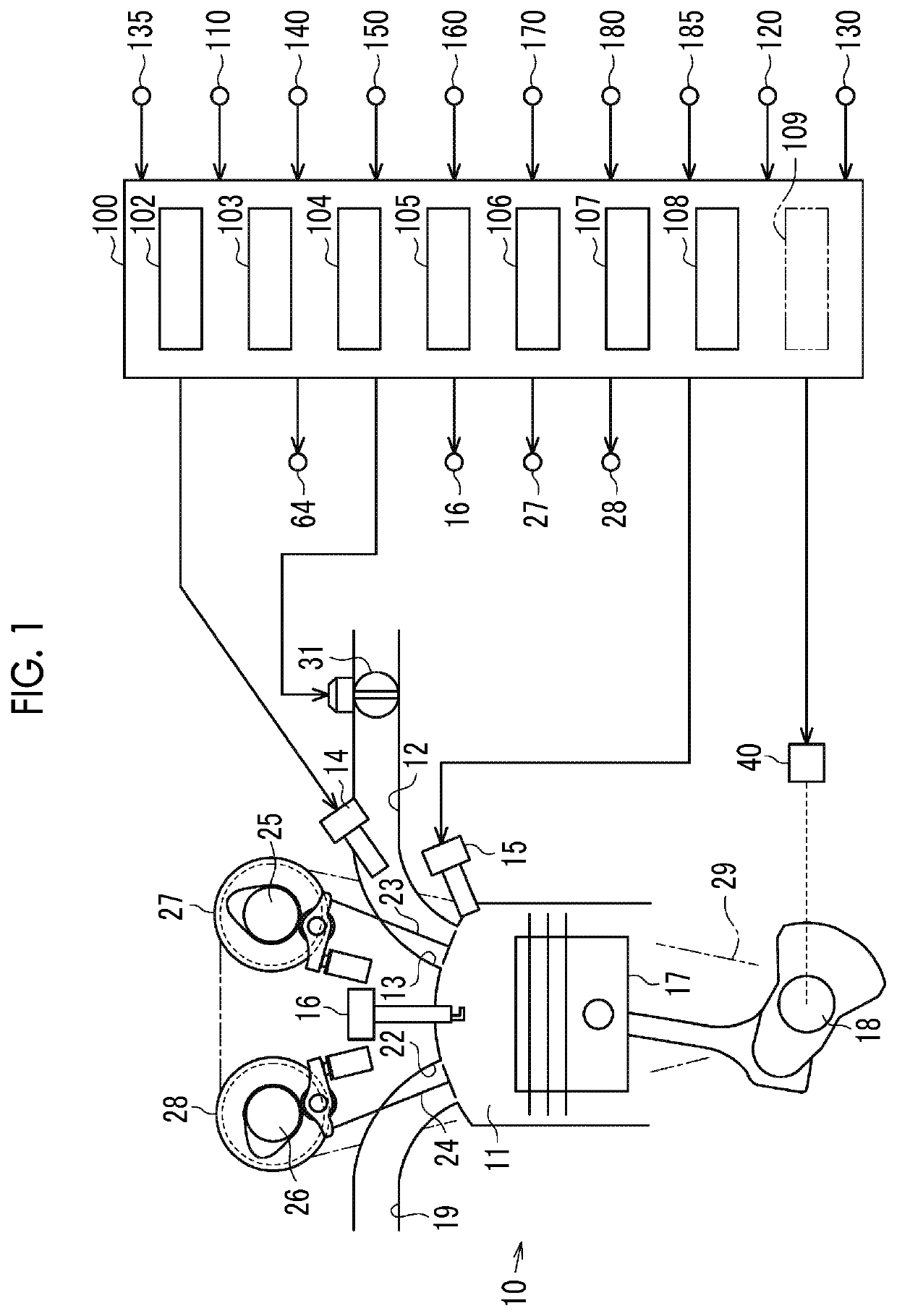
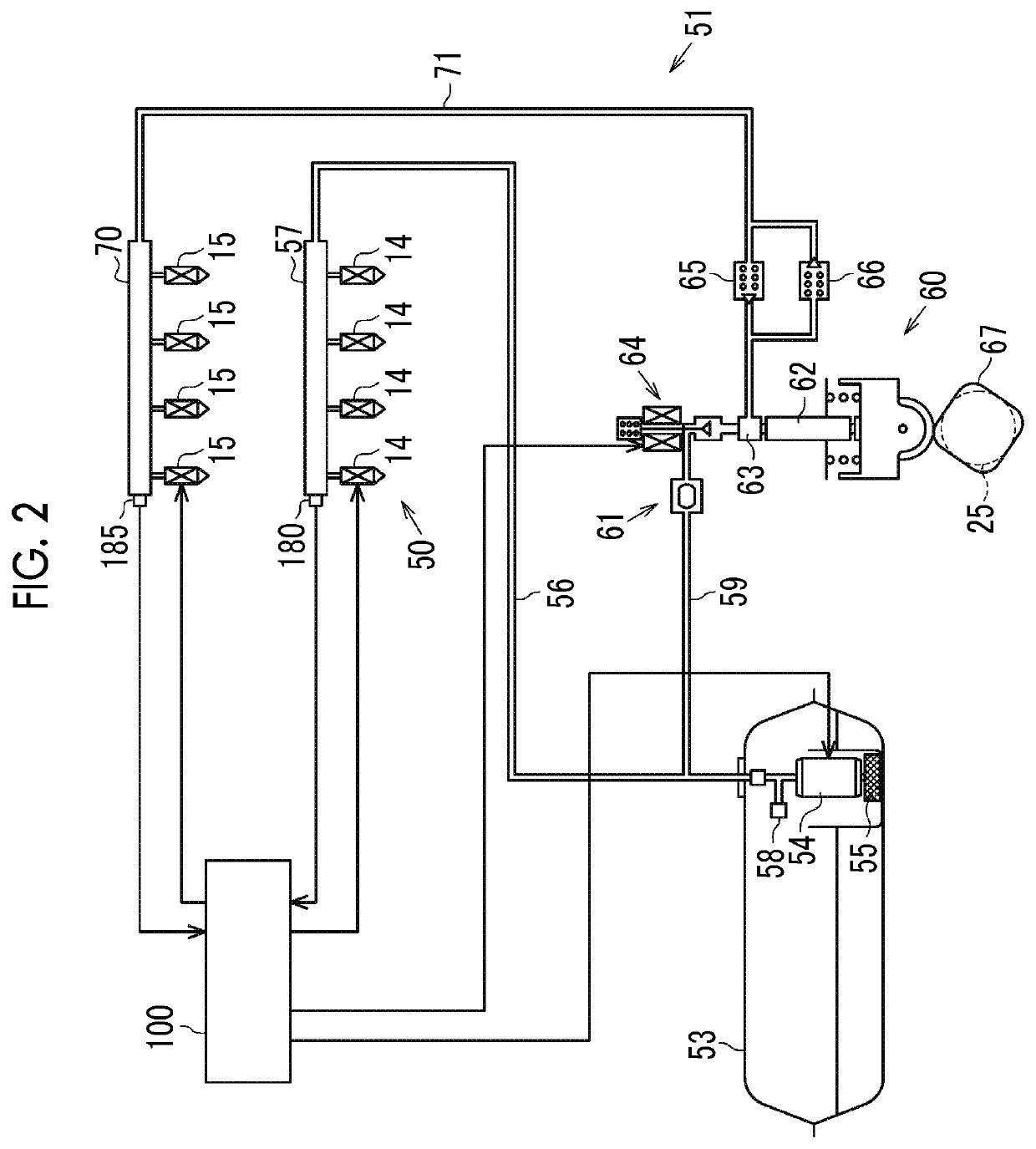
[0040]Hereinafter, an embodiment of a control system for an internal combustion engine will be described with reference to FIG. 1 to FIG. 16. The control system includes a controller 100. As shown in FIG. 1, an intake port 13 of an internal combustion engine 10 controlled by the controller 100 is provided with a port injection valve 14 for injecting fuel during an intake air flowing in the intake port 13. The intake port 13 is connected to an intake passage12. The intake passage 12 is provided with a throttle valve 31.

[0041]Additionally, a combustion chamber 11 is provided with an in-cylinder fuel injection valve 15 for directly injecting the fuel into the combustion chamber 11 and an ignition device 16 for igniting an air-fuel mixture of the air and the fuel introduced into the combustion chamber 11 by a spark discharge. An exhaust passage 19 is connected to the combustion chamber 11 via an exhaust port 22.

[0042]The internal combustion engine 10 is an in-vehicle internal combustion...


PUM


Abstract

A control system includes a controller. The controller estimates the swing-back amount indicating the turning amount of the crankshaft in the reverse rotation direction until the crankshaft stops. The controller calculates a stop-time counter value which is a value of a crank counter at the time when the engine is stopped based on a final counter value which is the value of the crank counter calculated last before the crankshaft stops and the estimated swing-back amount. The controller corrects the swing-back amount used for calculating the stop-time counter value based on a difference between the number of driving times calculated with reference to the map based on the calculated stop-time counter value and the value of the crank counter and the number of driving times calculated by increasing the number of driving times by one each time the high pressure system fuel pressure increases by the threshold or more.

Description

CROSS-REFERENCE TO RELATED APPLICATION[0001]This application claims priority to Japanese Patent Application No. 2019-074836 filed on Apr. 10, 2019, incorporated herein by reference in its entirety.BACKGROUND1. Technical Field[0002]The disclosure relates to a control system for an internal combustion engine, and the internal combustion engine.2. Description of Related Art[0003]Japanese Unexamined Patent Application Publication No. 2013-092116 (JP 2013-092116 A) discloses a controller for an internal combustion engine that stores a crank angle at the time when an engine is stopped and performs control at the time when the engine is started based on the stored crank angle. At the time when the engine is stopped, a crankshaft may swing in the reverse rotation direction due to the reaction force of the air compressed in a cylinder to recover.[0004]JP 2013-092116 A describes the controller that calculates turning amount of the crankshaft in the reverse rotation direction, that is, swing-b...

Claims


Application Information

Patent Timeline
IPC IPC(8): F02M59/10F02M61/14F02D41/00F02M59/22
CPCF02M61/14F02M59/22F02M59/10F02D41/009F02D45/00F02M65/00F02D2200/0604F02D2250/14F02D2250/31F02D2041/0092F02D2041/0095F02D2250/06F02D41/3845F02D41/062F02D41/3094
Inventor KATO, DAIKIKURODA, RYUSUKEIDOGAWA, MASANAO
Owner TOYOTA JIDOSHA KK
Why Eureka
Try Eureka