Electrical Connection, In Particular For An Electrically Heatable Honeycomb Body

a honeycomb body and electrical connection technology, applied in the direction of heater elements, machines/engines, mechanical equipment, etc., can solve the problems of low resistance of generally compressed materials, creepage currents, and known connections, so as to increase the amount of torque that can be absorbed, increase the size of the friction area, and improve the gas tightness of the connection

Active Publication Date: 2020-10-08
VITESCO TECH GERMANY GMBH
View PDF0 Cites 0 Cited by
  • Summary
  • Abstract
  • Description
  • Claims
  • Application Information

AI Technical Summary

Benefits of technology

The patent text discusses a design for a connector that prevents electrical arcing and increases the amount of torque that can be absorbed while also being compact and space-saving. This is achieved by using an insulation gap and surface structures that increase friction areas between the conductor, insulation, and bushing. The connector is designed using an internal thread, making it easier to design and manufacture.

Problems solved by technology

Problems occur in the known connections, specifically during operation of an electrical honeycomb body above a 48 V voltage supply.
In particular, creepage currents can occur that bridge the insulation between the electrical conductor and the bushing.
The cause of this is, for example, the low resistance of the generally compressed materials, which are used, to the influence of moisture, and also a low gas-tightness.
Furthermore, it is known that these connections have a low resistance in respect of the torques to be transmitted which occur, for example, when fastening a feed line.

Method used


Image

  • Electrical Connection, In Particular For An Electrically Heatable Honeycomb Body

Examples


Embodiment Construction

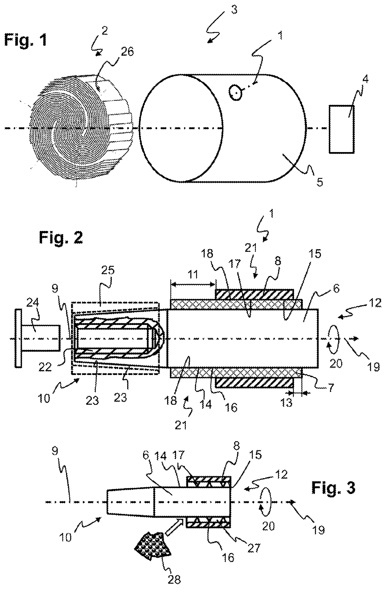
[0038]FIG. 1 shows an exploded illustration and perspective view of an internal combustion engine 4 comprising an exhaust gas system 3. The exhaust gas system 3 is a section of an exhaust gas line of a motor vehicle, in which section an electrically heatable honeycomb body is arranged as the electrical component 2. The exhaust gas line forms the casing 5 through which the conductor 6 of the electrical connection 1 extends along the center axis 9. The conductor 6 serves for making electrically conductive contact with an electrically conductive structural part 26 of the component 2 inside the casing 5. Outside the casing 5, the electrical connection 1 is connected to a voltage supply by a connection piece 25 and an electrical line at the first end 10 (see FIG. 2).

[0039]FIG. 2 shows a sectioned side view of an electrical connection 1. The connection 1 has the conductor 6 and also an electrical insulation 7, which surrounds the conductor 6, and a metal bushing 8, which surrounds the ins...


PUM


Abstract

An electrical connection for an electrical component in an exhaust gas system. The exhaust gas system has a metal casing through which an electrical conductor is routed. The connection has the conductor, an electrical insulation surrounding the conductor, and a metal bushing surrounding the insulation and the conductor, all together extend along a center axis. The insulation extends along the center axis beyond the bushing by an insulation gap of at least 2 mm at least at a first end of the connection.

Description

CROSS REFERENCE TO RELATED APPLICATIONS[0001]This is a U.S. national stage of application No. PCT / EP2017 / 062171, filed on May 19, 2017. Priority is claimed on German Application No. DE102016209282.0, filed May 30, 2016, the content of which is incorporated herein by reference.BACKGROUND OF THE INVENTION1. Field of the Invention[0002]The invention relates to electrical components in an exhaust gas system of an internal combustion engine, in particular of a motor vehicle. Modern exhaust gas purification systems often also contain electrical components, the supply lines of which have to be routed into the exhaust gas system from the outside in an electrically insulated manner. Particularly in the case of components that require relatively high currents, for example electrically heatable honeycomb bodies and the like, a relatively bulky electrical connection is required so that sufficiently high currents can be routed through.2. Description of the Prior Art[0003]A typical electrically h...

Claims


Application Information

Patent Timeline
Patent Type & Authority Applications(United States)
IPC IPC(8): F01N3/20F01N3/027F01N3/28H01R11/11
CPCH01R11/11F01N2330/02F01N3/027F01N3/2842F01N2240/16F01N3/2013F01N3/2026F01N3/01H05B3/08F01N2240/05H05B2203/024Y02T10/12
Inventor HIRTH, PETERHÃRIG, THOMASPABST, CHRISTOPH
Owner VITESCO TECH GERMANY GMBH
Why Eureka
Try Eureka