Eureka AIR delivers breakthrough ideas for toughest innovation challenges, trusted by R&D personnel around the world.

Sealing system

a sealing system and seal technology, applied in the direction of liquid fuel engines, machines/engines, mechanical equipment, etc., can solve the problems of water sulfide being extremely toxic, serious damage to the human body, and leakage to the outsid

Active Publication Date: 2020-10-01
EBARA CORP
View PDF0 Cites 3 Cited by
  • Summary
  • Abstract
  • Description
  • Claims
  • Application Information

AI Technical Summary

Benefits of technology

This patent describes a device that prevents leakage and reduction of sealing effect by using a fluid barrier-and-cooling medium. When the pressure in one chamber becomes higher than the other, the device reversely rotates to maintain pressure in the other chamber, preventing the fluid barrier-and-cooling medium from leaking to the atmosphere. This results in improved sealing and reduced risk of leakage.

Problems solved by technology

Hydrogen sulfide is extremely toxic.
If the hydrogen sulfide leaks into the atmosphere, it will cause serious damage to a human body.
Therefore, when the fluid, handled by the pump, contains a toxic or flammable fluid, such high-pressure dangerous fluid exists in the immediate vicinity of the atmospheric air, and may leakage to the outside.
Thus, when the fluid, handled by the pump, contains a toxic or flammable fluid, such a high-pressure dangerous fluid may leak to the outside.
If the heat is left as it is, it may cause interference between components or deformation of components due to thermal expansion, or may cause plastic deformation of sealing materials, such as O-rings 134, 135, thereby possibly impairing the sealing function.
As a result, the heat generated in the operation immediately before the stop is not dissipated, and temperatures of components around the pump mechanism 119 may rise to an unacceptable level.
As a result, the sealing effect is reduced, and the fluid barrier-and-cooling medium is likely to leak.

Method used


Image

  • Sealing system
  • Sealing system
  • Sealing system

Examples


Embodiment Construction

[0053]Embodiments of the present invention will be described below with reference to the drawings.

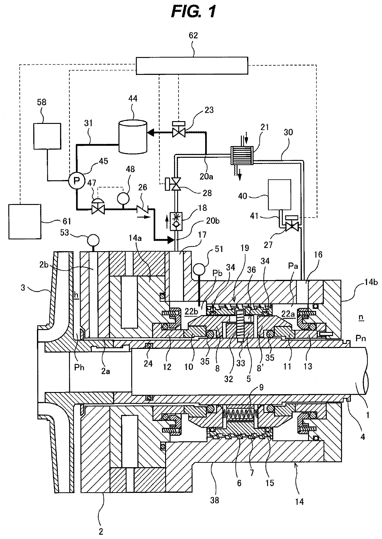
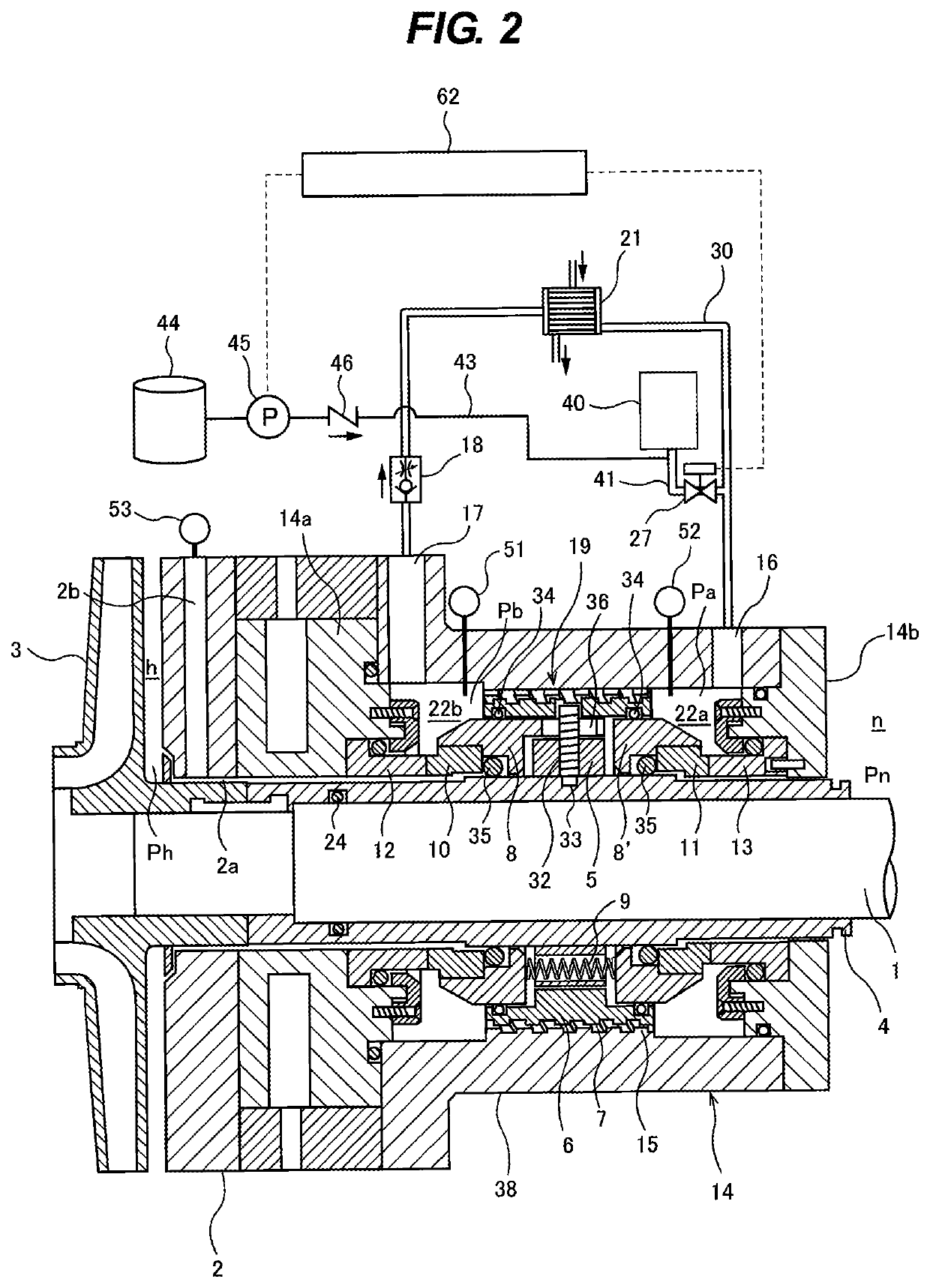
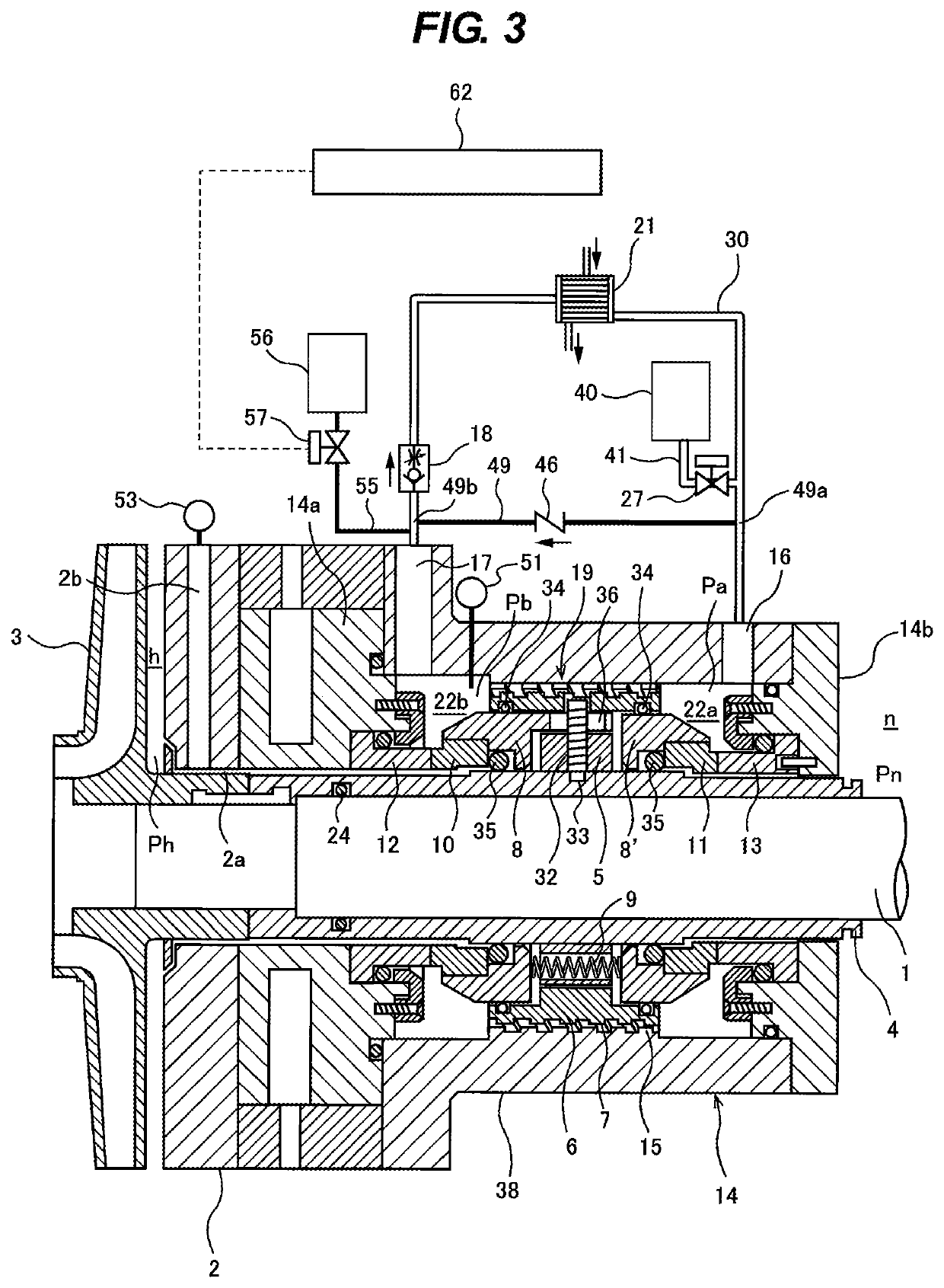
[0054]FIG. 1 is a view showing an embodiment of a sealing system including a double mechanical seal. The double mechanical seal has a function of sealing a gap between a rotational shaft 1 and a partition wall 2 that separates a high-pressure side h and a low-pressure side n.

[0055]In FIG. 1, at the high-pressure side h, a pump impeller 3 of a centrifugal pump is fixed to the rotational shaft 1, and a shaft sleeve 4 extends over an axial length of the double mechanical seal. The shaft sleeve 4 is fixed to an outer peripheral surface of the rotational shaft 1. An O-ring 24 is provided between the shaft sleeve 4 and the rotational shaft 1, and seals so as to prevent leakage of a fluid, handled by the centrifugal pump, through a gap between the shaft sleeve 4 and the rotational shaft 1. The fluid, handled by the centrifugal pump, contains a toxic fluid or a flammable fluid.

[0056]The pump im...


PUM


Abstract

A sealing system includes: a double mechanical seal having a pump-side sealing mechanism (10, 12) and an atmospheric-side sealing mechanism (11, 13); a pump mechanism (19) driven by a rotational shaft (1); a first medium circulation line (30) for circulating a fluid barrier-and-cooling medium between a first chamber (22a) and a second chamber (22b), the first medium circulation line (30) being coupled to the first chamber (22a) and the second chamber (22b), the fluid barrier-and-cooling medium being different from a fluid handled by the centrifugal pump; a heat exchanger (21) and a shut-off valve (28) attached to the first medium circulation line (30); a second medium circulation line (31) bypassing the shut-off valve (28); and a medium pressurizing pump (45) and an on-off valve (23) attached to the second medium circulation line (31).

Description

TECHNICAL FIELD[0001]The present invention relates to a sealing system including a double mechanical seal provided in a seal housing, and more particularly relates to a sealing system having a pump mechanism driven by a rotational shaft wherein the pump mechanism is provided between a pump-side sealing mechanism and an atmospheric-side sealing mechanism constituting a double mechanical seal.BACKGROUND ART[0002]When fossil fuels, such as oil and natural gas, are refined, it is necessary to remove impurities, such as carbon dioxide (CO2) and sulfur (S). Sulfur is often recovered as hydrogen sulfide (H2S) in a refining process. A fluid, handled by a pump used in the refining process, may contain a lot of hydrogen sulfide. Hydrogen sulfide is extremely toxic. If the hydrogen sulfide leaks into the atmosphere, it will cause serious damage to a human body. Therefore, it is necessary to pay full attention to design a pump that handles hydrogen sulfide so that the hydrogen sulfide never lea...

Claims


Application Information

Patent Timeline
IPC IPC(8): F04D29/12F04D29/14F04D29/58
CPCF04D29/143F04D29/124F16J15/34F04D29/582F04D29/126F04D29/586F04D29/128F04D29/588F04D1/00F16J15/3492F16J15/3404F16J15/406
Inventor YOSHIKAWA, SHIGERUHAYAKAWA, JUNICHI
Owner EBARA CORP
Why Eureka
Eureka Blog
Learn More