Return flow system for ion concentration polarization (ICP) desalination
a technology of ion concentration polarization and flow system, which is applied in the direction of separation process, dispersed particle separation, chemistry apparatus and processes, etc., can solve the problems of flow barrier and increase in the traveling length of the stream, and achieve the effect of suppressing or preventing the propagation of highly enriched salts, maximizing pressure difference, and suppressing chaotic electroconvection
- Summary
- Abstract
- Description
- Claims
- Application Information
AI Technical Summary
Benefits of technology
Problems solved by technology
Method used
Image

Examples
example 1
ow Ion Concentration Polarization Desalination: A New Way to Enhance Electromembrane Desalination
[0152]A novel return flow (RF) electromembrane desalination process was developed where direct control of flow path effectively limits the growth of ion depletion region, therefore resulting in both high salt removal and high energy efficiency. FIG. 11D shows a schematic illustration of RF-ICP desalination with three channels separated by two porous membranes. RF-ICP has the same channel architecture as Tri-ICP, which has the three channels composed of a concentrate channel on the anodic side, a diluate channel on the cathodic side and an intermediate channel between them. However, the intermediate channel outlet of Tri-ICP is replaced by the feed inlet of RF-ICP, and the feed inlet of Tri-ICP is entirely closed. Due to the course of flow and its pressure distribution by the channel configuration, two flows appear as follows (FIG. 11F): firstly, the channel configuration results in a flo...
example 2
low Ion Concentration Polarization (CF-ICP)
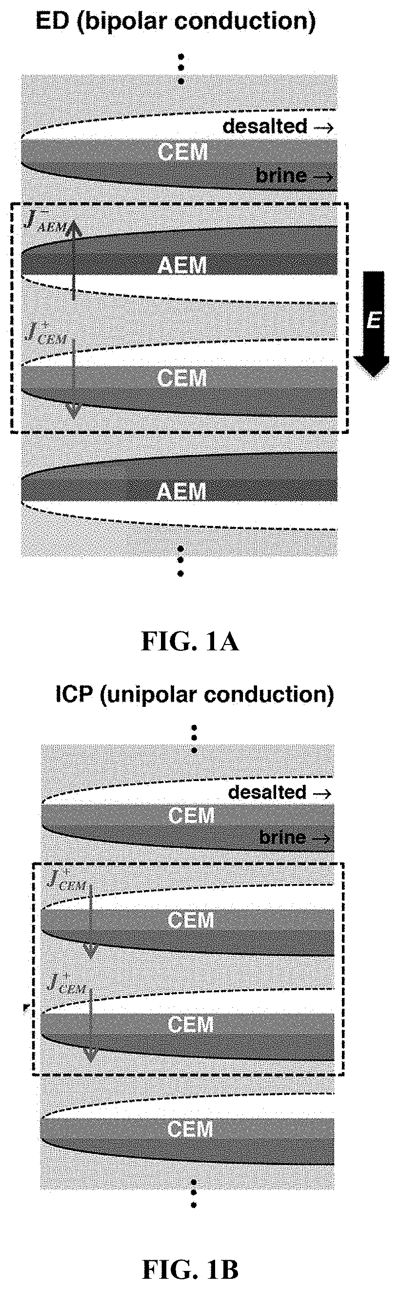
[0183]ICP desalination is created by employing a unipolar membrane system (e.g. only using CEMs), which will create two zones (brine and desalted) within the channel between the membranes. In ICP desalination, separation of brine and desalted flow is achieved by the fluidic split at the end of the system. A high-flow scale-up (shown in FIGS. 29 to 33) can be achieved by stacking CEMs in a similar manner to a conventional electrodialysis (ED). FIGS. 29 to 33 compare the bifurcate ICP (Bi-N) with the CF-ICP (referred to as “Bi-C” in FIGS. 29 to 33). Concentration profile, Current utilization, and Power Consumption were measured as described above in Example 1.
[0184]To evaluate the feasibility of Bi-C for desalination, concentration changes in diluate and concentrate streams for both systems (Bi-N and Bi-C) were measured under an application of current flux (FIG. 30). Both systems show symmetrical changes in concentration profiles and Bi-C pro...
example 3
n of Power Efficiency by Various ICP Process Architectures (Spacers)
[0188]We have introduced various spacers, Bi-ICP (bifurcate normal flow), Tri-ICP (trifurcate ICP), RF-ICP (return flow ICP) and CF-ICP (counter flow ICP), for ICP desalination (FIGS. 9A-9D) and their unique features are summarized in Table 3. In order to evaluate the energy efficiency of different ICP process architectures (which differ by the kind of spacer design / engineering that is used), we obtained the power consumption as a function of salt removal ratio (SRR) with 70, 100 and 160 g / L of feed salinity in FIGS. 10A-10C. The original ICP architecture called “Bi-ICP” (FIG. 9A) is able to separate and collect two streams, diluate and concentrate streams. Bi-ICP requires the highest power consumption among the spacers, given the same conditions. Because Bi-ICP simultaneously collects a large amount of streams including a thick bulk layer and a thin depletion layer. Then, Tri-ICP (FIG. 9B) facilitates the collectio...
PUM
| Property | Measurement | Unit |
|---|---|---|
| length | aaaaa | aaaaa |
| current flux | aaaaa | aaaaa |
| concentration | aaaaa | aaaaa |
Abstract
Description
Claims
Application Information
 - R&D
- Intellectual Property
- Life Sciences
- Materials
- Tech Scout
- Unparalleled Data Quality
- Higher Quality Content
- 60% Fewer Hallucinations
Browse by: Latest US Patents, China's latest patents, Technical Efficacy Thesaurus, Application Domain, Technology Topic, Popular Technical Reports.
© 2025 PatSnap. All rights reserved.Legal|Privacy policy|Modern Slavery Act Transparency Statement|Sitemap|About US| Contact US: help@patsnap.com