
Electromechanical Spring System

Pending Publication Date: 2020-09-24
BARNES GROUP
View PDF7 Cites 6 Cited by
  • Summary
  • Abstract
  • Description
  • Claims
  • Application Information

AI Technical Summary

Benefits of technology

The patent text describes a spring system that includes a housing and a rod engagement element. The telescoping tube cover serves as a spring guide and can be used with different types of sleeves. The rod engagement element can be supported with a longer element / sleeve to increase the buckling force and shorten the screw / lead component. This is useful when the spring system needs to be compact or when the spring is not designed for a certain type of application. Overall, the technical effects of the patent text allow for a more compact and efficient spring system that can be used in a variety of applications.

Problems solved by technology

These large spring systems typically have a large footprint due to the large springs used in the spring system and / or the complicated hydraulic systems used with the spring system.
However, when the motor disengages or breaks, the spring system become inoperable.

Method used


Image

  • Electromechanical Spring System
  • Electromechanical Spring System
  • Electromechanical Spring System

Examples


Embodiment Construction

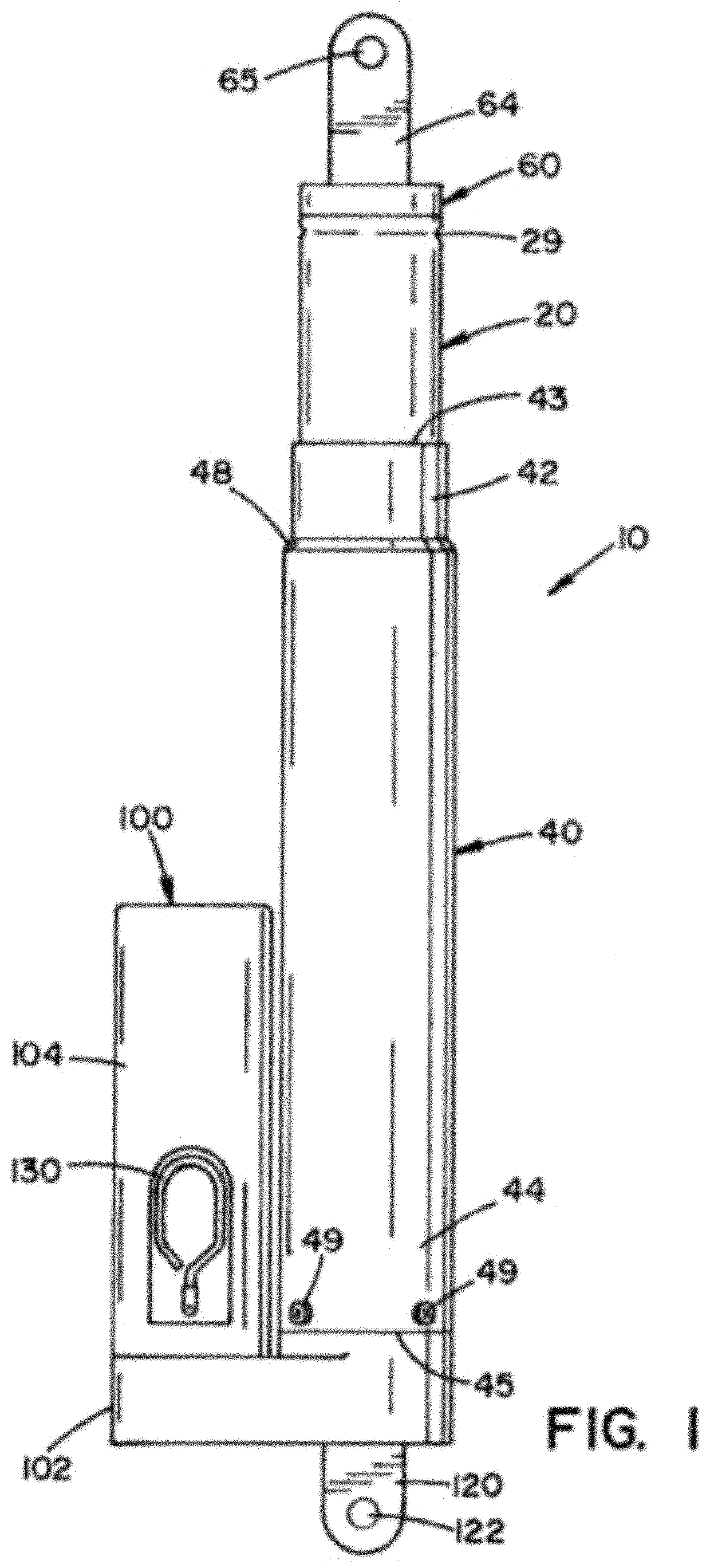
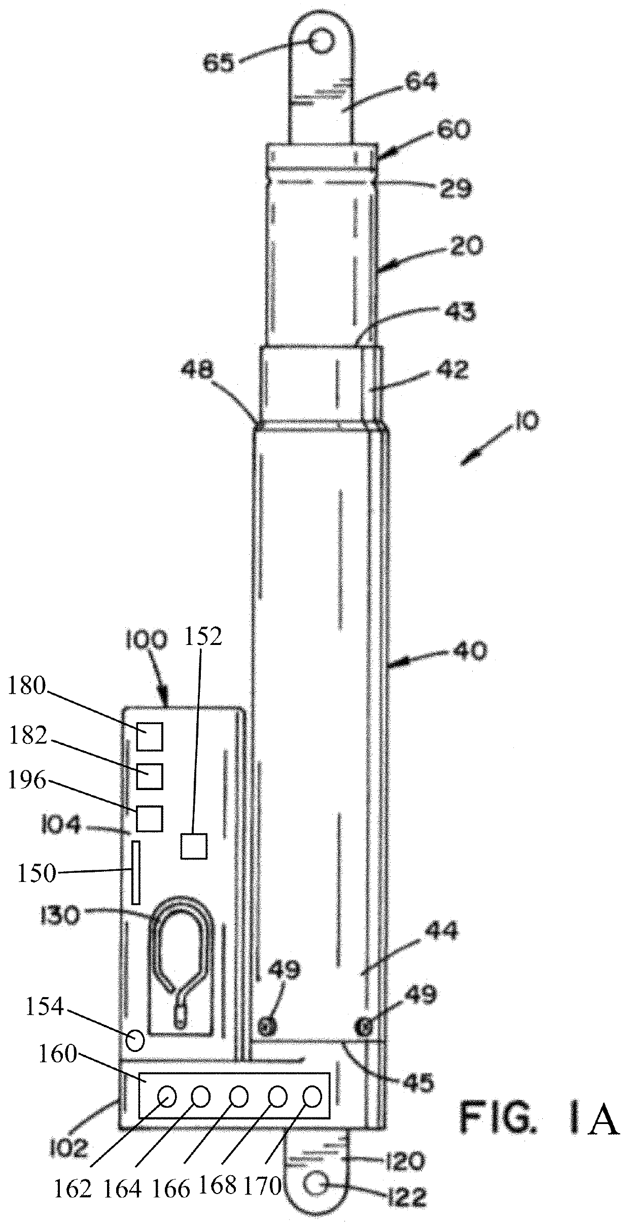
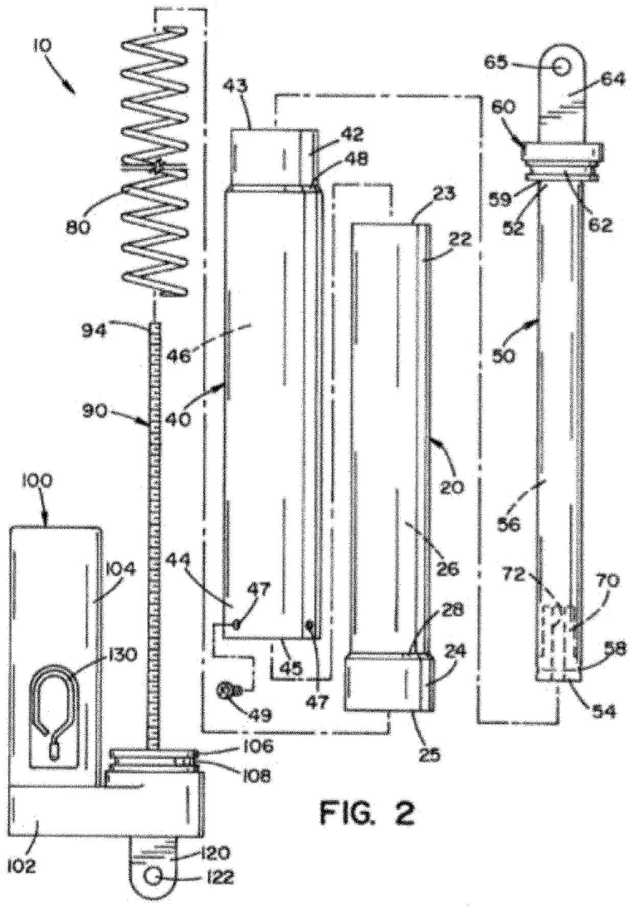
[0136]A more complete understanding of the articles / devices, processes, and components disclosed herein can be obtained by reference to the accompanying drawings. These figures are merely schematic representations based on convenience and the ease of demonstrating the present disclosure, and are, therefore, not intended to indicate relative size and dimensions of the devices or components thereof and / or to define or limit the scope of the exemplary embodiments.

[0137]Although specific terms are used in the following description for the sake of clarity, these terms are intended to refer only to the particular structure of the embodiments selected for illustration in the drawings and are not intended to define or limit the scope of the disclosure. In the drawings and the following description below, it is to be understood that like numeric designations refer to components of like function.

[0138]The singular forms “a,”“an,” and “the” include plural referents unless the context clearly d...


PUM


Abstract

A spring system that includes an adjustable spring system that is operated by a motor.

Description

[0001]The present disclosure is a continuation-in-part of U.S. patent application Ser. No. 14 / 850,134 filed Sep. 10, 2015, which in turn claims priority on U.S. Provisional Patent Application Ser. No. 62 / 052,554 filed Sep. 19, 2014, which is incorporated herein by reference.[0002]The present disclosure relates to spring systems, particularly to a spring assembly that includes an adjustable spring system, and more particularly to a spring assembly that includes an adjustable spring system that is operated in tandem with a motor. The spring system of the present disclosure can be used in the medical field, automotive industry, manufacturing industry, building industry, etc. The spring system of the present disclosure can include one or more mechanical springs and / or include a compressible or non-compressible fluid. The spring system of the present disclosure can include one or more mechanical springs and / or include a compressible or non-compressible fluid that can optionally be config...

Claims


Application Information

Patent Timeline
IPC IPC(8): F16F1/04F16H25/20H04L29/08G05B19/042G05D15/01
CPCF16H2025/2081F16F2230/18G05B2219/25065F16F2230/0047H04L67/125F16F2232/08F16H2025/2071G05D15/01F16F2228/08F16F2230/0023G16Y40/30F16H2025/2046F16F1/041G16Y20/20G05B19/0426F16H25/2021F16H25/20
Inventor VINE, ADRIAN A.THOMPSON, ROBERT D.ROCKOW, STEVEN F.REYNARD, CHRISTOPHER T.ADOLINE, JACK W.MCCONNELL, PHILLIP A.
Owner BARNES GROUP
Learn More