Semiconductor device
a technology of semiconductor elements and sealing materials, applied in semiconductor devices, semiconductor/solid-state device details, electrical devices, etc., can solve the problems of reducing the reliability of the semiconductor device, peeling the small area of adhesion between the sealing material and the insulating substrate, etc., to achieve the effect of increasing the packaging density of semiconductor elements, reducing size, and reducing siz
- Summary
- Abstract
- Description
- Claims
- Application Information
AI Technical Summary
Benefits of technology
Problems solved by technology
Method used
Image
Examples
first embodiment
[0027]
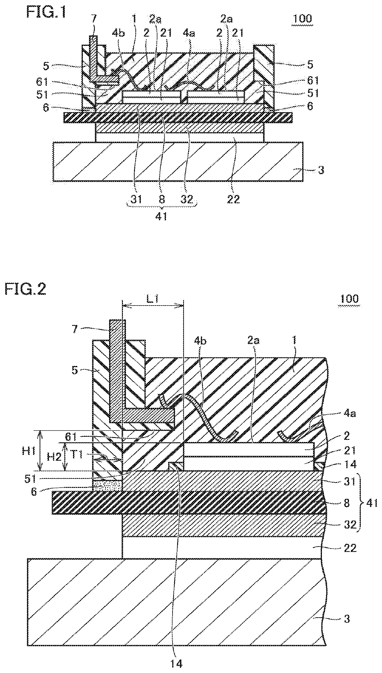
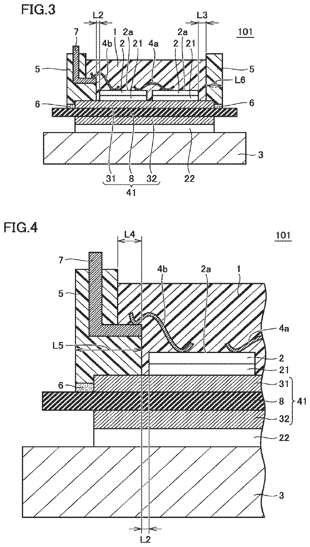
[0028]FIG. 1 is a schematic cross-sectional view showing a basic structure of a semiconductor device according to a first embodiment of the present invention. FIG. 2 is a schematic fragmentary cross-sectional view of the semiconductor device shown in FIG. 1. The configuration of the semiconductor device according to the first embodiment of the present invention is described with reference to FIGS. 1 and 2. A semiconductor device 100 shown in FIGS. 1 and 2 is a semiconductor power module used for industrial purposes or for automobiles, for example.
[0029]Referring to FIG. 1, semiconductor device 100 mainly includes an insulating substrate 41, a metal base plate 3, semiconductor elements 2 joined on insulating substrate 41, wiring members 4a, 4b, a case member 5 surrounding semiconductor elements 2, an electrode terminal 7, and a sealing resin 1. Case member 5 is connected to insulating substrate 41 by an adhesive 6. Case member 5 is provided with a recess 51 on its inner surface...
second embodiment
[0062]
[0063]FIG. 8 is a schematic cross-sectional view showing a basic structure of a semiconductor device 200 according to a second embodiment of the present invention. The configuration of semiconductor device 200 according to the second embodiment of the present invention is described with reference to FIG. 8.
[0064]As shown in FIG. 8, semiconductor device 200 is basically configured similarly to the semiconductor device shown in FIGS. 1 and 2, but is different from semiconductor device 100 shown in FIGS. 1 and 2 in that it has a through hole 9 provided in case member 5. That is, semiconductor device 200 shown in FIG. 8 is provided with through hole 9 extending from inside recess 51 to an upper end of case member 5.
[0065]
[0066]Semiconductor device 200 shown in FIG. 8 can basically produce similar effects to those of semiconductor device 100 shown in FIG. 1. Further, in semiconductor device 200 shown in FIG. 8, through hole 9 provided in case member 5 extends through case member 5 ...
third embodiment
[0076]
[0077]FIG. 12 is a schematic cross-sectional view showing a basic structure of a semiconductor device 300 according to a third embodiment of the present invention. The configuration of semiconductor device 300 according to the third embodiment of the present invention is described with reference to FIG. 12.
[0078]As shown in FIG. 12, semiconductor device 300 is basically configured similarly to semiconductor device 200 shown in FIG. 8, but is different from semiconductor device 200 shown in FIG. 8 in the shape of the inner wall of recess 51. That is, in semiconductor device 300 shown in FIG. 12, facing surface 61 of recess 51 facing insulating substrate 41 is inclined relative to the front surface of insulating layer 8 or the surface of first circuit board 31. In other words, facing surface 61 of recess 51 is a surface inclined such that its distance from insulating layer 8 or first circuit board 31 increases gradually from the end on the outer peripheral side to the end on the...
PUM
| Property | Measurement | Unit |
|---|---|---|
| Distance H1 | aaaaa | aaaaa |
| Distance H1 | aaaaa | aaaaa |
| distance H1 | aaaaa | aaaaa |
Abstract
Description
Claims
Application Information
 - R&D
- Intellectual Property
- Life Sciences
- Materials
- Tech Scout
- Unparalleled Data Quality
- Higher Quality Content
- 60% Fewer Hallucinations
Browse by: Latest US Patents, China's latest patents, Technical Efficacy Thesaurus, Application Domain, Technology Topic, Popular Technical Reports.
© 2025 PatSnap. All rights reserved.Legal|Privacy policy|Modern Slavery Act Transparency Statement|Sitemap|About US| Contact US: help@patsnap.com


