Method and apparatus for safely and quickly removing snow from narrow pedestrian and vehicular paths

a pedestrian and vehicular path technology, applied in the field of snow removal, can solve the problems of outperforming ride-on style snow blowers, walking-behind snow blowers have substantial risk of falling, and require substantial upper body strength to turn, so as to improve the efficiency of snow removal, and improve the effect of snow removal efficiency

Active Publication Date: 2020-09-03
BECWAR BRIAN DALE
View PDF0 Cites 0 Cited by
  • Summary
  • Abstract
  • Description
  • Claims
  • Application Information

AI Technical Summary

Benefits of technology

The present invention is a snow blower machine designed to be efficient and cost-effective. It is designed to address the needs of projects where the machine is only four feet wide. The machine has a centrally stowed hand shovel that can be easily accessed from either side when stepping off the machine. It can address very short and frequent detailed hand shoveling tasks quickly and minimize the effort, and often danger, of walking during the snow removal process. The machine also includes a winch for elevating the snow blower head and a snow blower head load bearing pin to maintain an elevated position of the snow blower head while permitting use of the winch for other purposes. The method of removing snow using the machine involves the steps of using the machine to clear the snow and using the winch to elevate the snow blower head.

Problems solved by technology

Often these walk-behind snow blowers have substantial risk of slipping and falling, especially when the surface to be cleared is slippery.
These walk-behind snow blowers often require substantial upper body strength to turn.
Such designs would provide a more massive system which, in certain situations such as in deep snow, might outperform walk-behind snow blowers and, with projects requiring many stops, e.g. to do hand shoveling, they can often outperform the ride-on style snow blowers.
While these types of stand-on snow blowing systems may have many advantages in particular applications, they also have some drawbacks.
For example, in many sidewalk snow removal projects, it is often not practical to use such 4×4 systems if the sidewalk is only four (4) feet wide.
These 4×4 systems are typically not capable of turning around completely on the sidewalk.
This can be especially problematic for these heavy systems if these sidewalks are directly adjacent to very delicate areas, such as areas with exposed or shallow irrigation systems.

Method used


Image

  • Method and apparatus for safely and quickly removing snow from narrow pedestrian and vehicular paths
  • Method and apparatus for safely and quickly removing snow from narrow pedestrian and vehicular paths
  • Method and apparatus for safely and quickly removing snow from narrow pedestrian and vehicular paths

Examples


Embodiment Construction

[0050]Although described with particular reference to a stand-on snow blower, (such as a 2×4 with one powered wheel and one unpowered caster per side) the system and method for removing snow can be implemented in many different types of stand-on snow blowers with only two powered wheels.

[0051]In an embodiment, the system and method for removing snow can be implemented on a ride-on machine which is capable of receiving a snow blower or a snow broom.

[0052]The details below should be viewed as examples of many potential variations of the present invention which are protected hereunder.

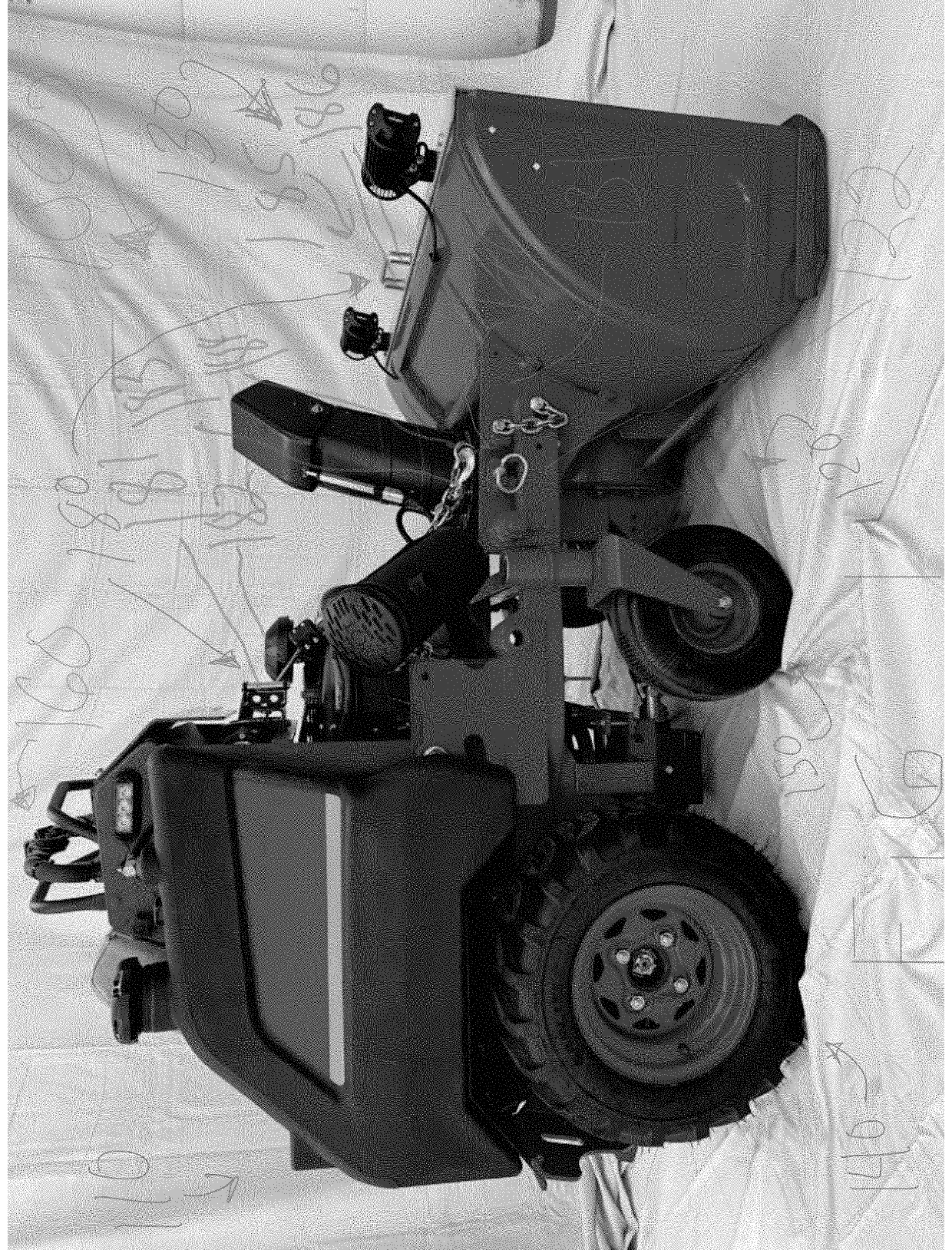
[0053]FIG. 1 is a side view of the stand-on snow blower, generally designated 100 of the present invention, which includes a rear operator stand-on portion 110, which can, in many ways, be identical to a rear operator stand-on portion of a V Ride 2 power mower manufactured by Scag Power Equipment of Mayville, Wis., or a suitable substitute. Also shown are: mid caster and attachment zone 120, snow blower h...


PUM


Abstract

A method and system is disclosed which provides for a zero turn stand-on snow blower with only two powered wheels and two free wheeling casters which provides for the ability to blow snow from narrow paths, turn around without leaving the sidewalk, automatically turn off the auger and present a shovel for performing quick detailed shoveling tasks when stepping off the snow blower.

Description

FIELD OF THE INVENTION[0001]The present invention generally relates to snow removal, and more particularly relates to commercial use snow blowers and, even more particularly, relates to rapid snow removal using zero-turn stand-on snow blowers.BACKGROUND OF THE INVENTION[0002]In the past, walk-behind snow blowers have been used by homeowners as well as commercial snow removal companies. Often these walk-behind snow blowers have substantial risk of slipping and falling, especially when the surface to be cleared is slippery. These walk-behind snow blowers often require substantial upper body strength to turn. Both stand-on and sit-on versions of ride-on snow blowers require much less walking, and therefore have less risk inherent to walking and also require less physical exertion for turning, but the effort and time required to get in and out of the seat of a sit-on can be substantial. Stand-on snow blowers have been well received for several reasons, including the ability to be mounte...

Claims


Application Information

Patent Timeline
IPC IPC(8): E01H5/04E01H5/02E01H5/09
CPCE01H5/02E01H5/098E01H5/045
Inventor BECWAR, BRIAN DALE
Owner BECWAR BRIAN DALE
Why Eureka
Try Eureka