
Circulating coolant fluid in hybrid electrical propulsion systems

a technology of electrical propulsion system and coolant fluid, which is applied in the direction of lubricant mounting/connection, turbines, depending on power plant types, etc., can solve the problem that the engine is in effect oversized for the relatively low power required to produ

Active Publication Date: 2020-09-03
PRATT & WHITNEY CANADA CORP
View PDF0 Cites 11 Cited by
  • Summary
  • Abstract
  • Description
  • Claims
  • Application Information

AI Technical Summary

Benefits of technology

This patent describes a hybrid propulsion system for vehicles that uses both a heat engine and an electric motor to provide power. The system has a coolant system that circulates fluid through the heat engine and the electric motor for cooling. The system also includes a turbine gearbox and a combining gearbox to combine the power from the heat engine and the electric motor. The coolant system has separate lubricant / coolant sub-lines for the heat engine and the electric motor, with scavenge passages and pumps to keep the fluids circulating. The system also has a chip detector and a pressure pump to manage the coolant flow. Overall, the system provides efficient cooling and power combination for vehicles.

Problems solved by technology

The size and weight of the engines allows them to produce the power needed for take-off, however after take-off the engines are in effect over-sized for the relatively low power required to produce thrust for cruising in level flight.

Method used


Image

  • Circulating coolant fluid in hybrid electrical propulsion systems
  • Circulating coolant fluid in hybrid electrical propulsion systems
  • Circulating coolant fluid in hybrid electrical propulsion systems

Examples


Embodiment Construction

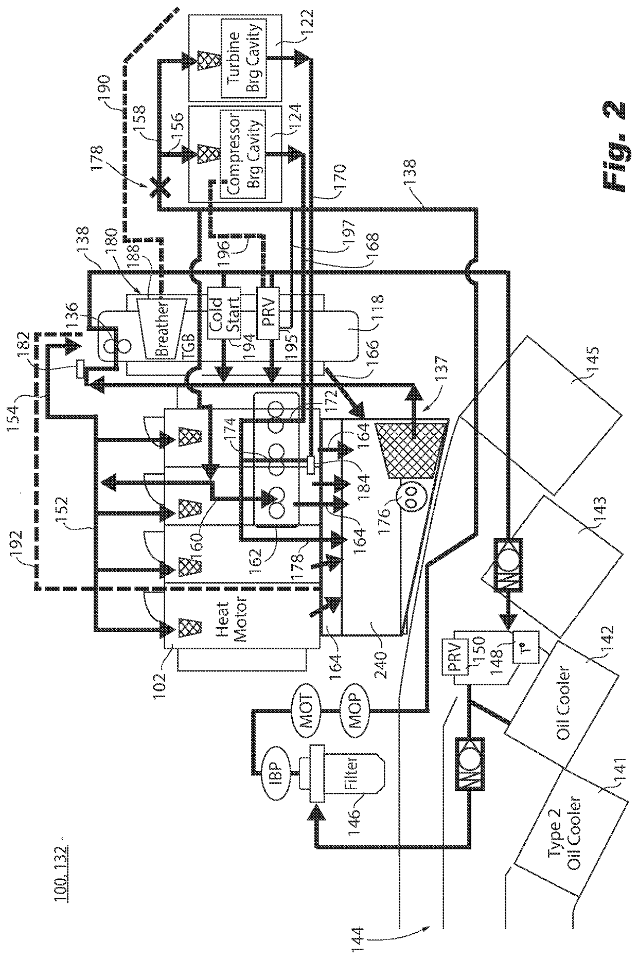
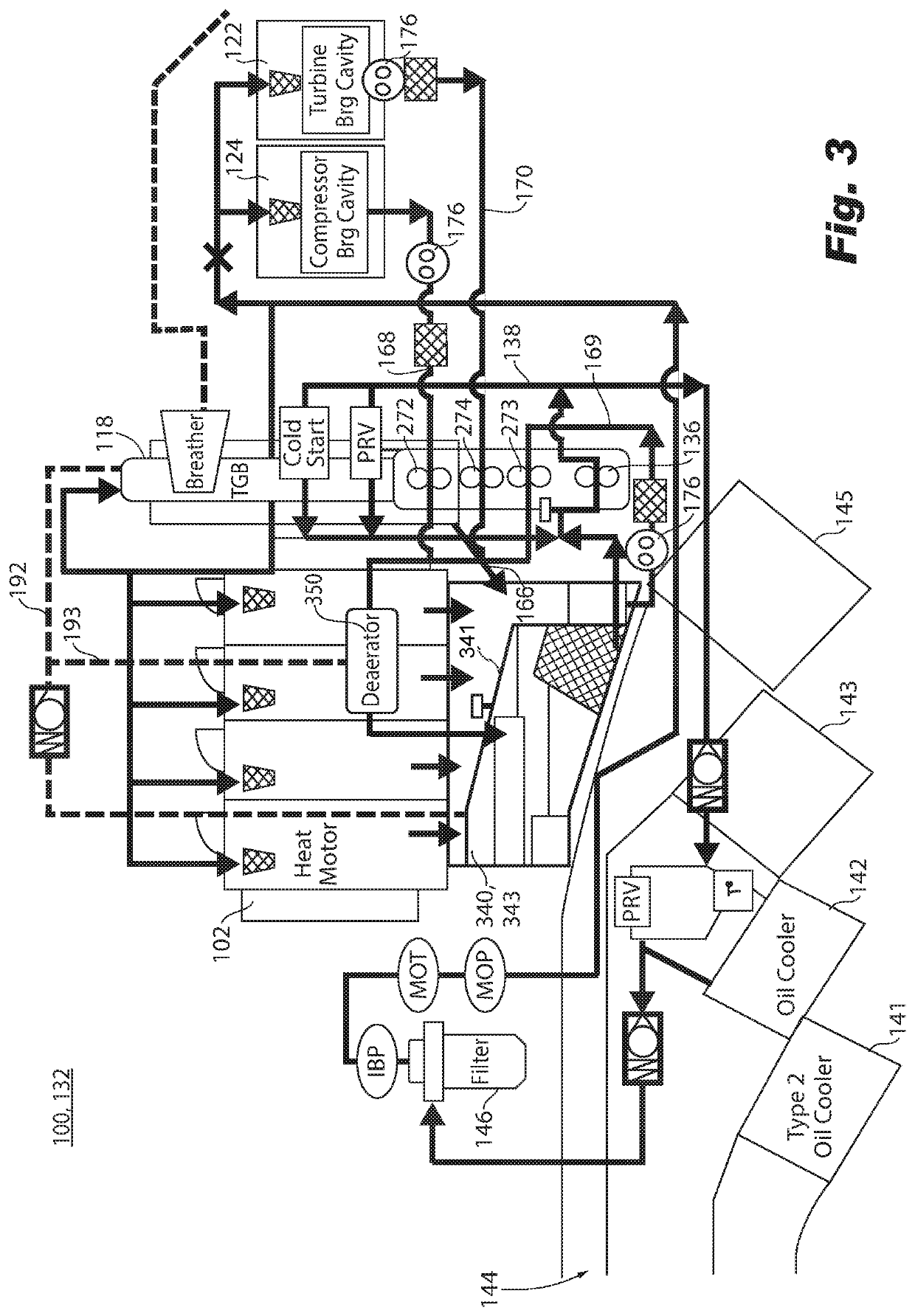
[0021]Reference will now be made to the drawings wherein like reference numerals identify similar structural features or aspects of the subject disclosure. For purposes of explanation and illustration, and not limitation, a partial view of an exemplary embodiment of the a hybrid propulsion system in accordance with the disclosure is shown in FIG. 1 and is designated generally by reference character 100. Other embodiments of systems in accordance with the disclosure, or aspects thereof, are provided in FIGS. 2-5, as will be described. The systems and methods described herein can be used to provide hybrid propulsion, e.g., for improving fuel efficiency in aircraft.

[0022]The hybrid propulsion system 100 includes a heat engine 102 configured to drive a heat engine shaft 104. An electric motor 106 is configured to drive a motor shaft 108. A transmission system 110 is configured to receive rotational input power from each of the heat engine shaft 104 and the motor shaft 108 and to convert...


PUM


Abstract

A hybrid propulsion system includes a heat engine configured to drive a heat engine shaft. An electric motor configured to drive a motor shaft. A transmission system is connected to receive rotational input power from each of the heat engine shaft and the motor shaft and to convert the rotation input power to output power. A first lubrication / coolant system is connected for circulating a first lubricant / coolant fluid through the heat engine. A second lubricant / coolant system in fluid isolation from the first lubrication / coolant system is connected for circulating a second lubricant / coolant fluid through the electric motor.

Description

CROSS REFERENCE TO RELATED APPLICATIONS[0001]This application claims the benefit of and priority to U.S. Provisional Patent Application No. 62 / 812,439, filed Mar. 1, 2019, the disclosure of which is hereby incorporated by reference in its entirety.BACKGROUND OF THE INVENTION1. Field of the Invention[0002]The present disclosure relates to aircraft engines, and more particularly to hybrid aircraft engines.2. Description of Related Art[0003]Aircraft engines vary in efficiency and function over a plurality of parameters, such as thrust requirements, air temperature, air speed, altitude, and the like. Aircraft require the most thrust at take-off, wherein the demand for engine power is the heaviest. However, during the remainder of the mission, the aircraft engines often do not require as much thrust as during take-off. The size and weight of the engines allows them to produce the power needed for take-off, however after take-off the engines are in effect over-sized for the relatively low...

Claims


Application Information

Patent Timeline
IPC IPC(8): B64D33/08B64D35/02B64D27/02B64D27/24F01M11/00F01M5/00F01M1/02F01M1/10F01M11/03F16H57/04F01D25/18F01D25/12H02K7/116H02K9/19H02K9/26H02K11/25
CPCF01D25/12F01M11/0004F16H57/0476B64D35/02H02K7/116F01M11/03F16H57/0436F16H57/0475H02K11/25H02K9/19F01D25/18F16H57/0404B64D27/24F16H57/0416B64D33/08F01M2005/004F01M5/002F01M1/10B64D2027/026F01M2250/60H02K9/26F01M1/02B64D27/02F01M2011/038F01M2011/033F16N2210/02F16N2210/08F16N2210/12F01D25/20F02C7/06F02C7/36F02K5/00F05D2260/98F05D2260/213B64D27/026
Inventor DUBREUIL, JEANLATULIPE, ERIC
Owner PRATT & WHITNEY CANADA CORP
Learn More