Circular patch array for Anti-jam GPS

a patch array and patch antenna technology, applied in the field of anti-jam (aj) antenna technology, can solve the problems of inconvenient stacked patch antennas, high cost of grinding ceramic materials to match surface curvature, and significant problems with ceramic materials

Active Publication Date: 2020-08-27
BAE SYST INFORMATION & ELECTRONICS SYST INTERGRATION INC
View PDF0 Cites 1 Cited by
  • Summary
  • Abstract
  • Description
  • Claims
  • Application Information

AI Technical Summary

Problems solved by technology

In environments with conformal surface requirements, there are significant problems using ceramic materials.
First, grinding...

Method used


Image

  • Circular patch array for Anti-jam GPS
  • Circular patch array for Anti-jam GPS
  • Circular patch array for Anti-jam GPS

Examples


Embodiment Construction

[0028]In GPS systems, for ranging codes and navigation messages to travel from a satellite to a receiver, they must be modulated onto a carrier wave. According to the original GPS design, two frequencies are utilized; one at about 1575 MHz, called L1; and a second at about 1228 MHz, called L2. Military programs typically specify a minimum bandwidth of 24 MHz for M-Code GPS band waveform. A course / acquisition (C / A) code is transmitted on the L1 frequency as about a 1 MHz signal using a bi-phase shift keying (BPSK) modulation technique. An encrypted pseudorandom noise number (P(Y)-code) is transmitted on both the L1 and L2 frequencies as about a 10 MHz signal using the same BPSK modulation. However, the P(Y)-code carrier is in quadrature with the C / A carrier (meaning it is 90° out of phase).

[0029]Besides redundancy and increased resistance to jamming, a critical benefit of having two frequencies transmitted from one satellite is the ability to measure directly, and therefore remove, t...


PUM


Abstract

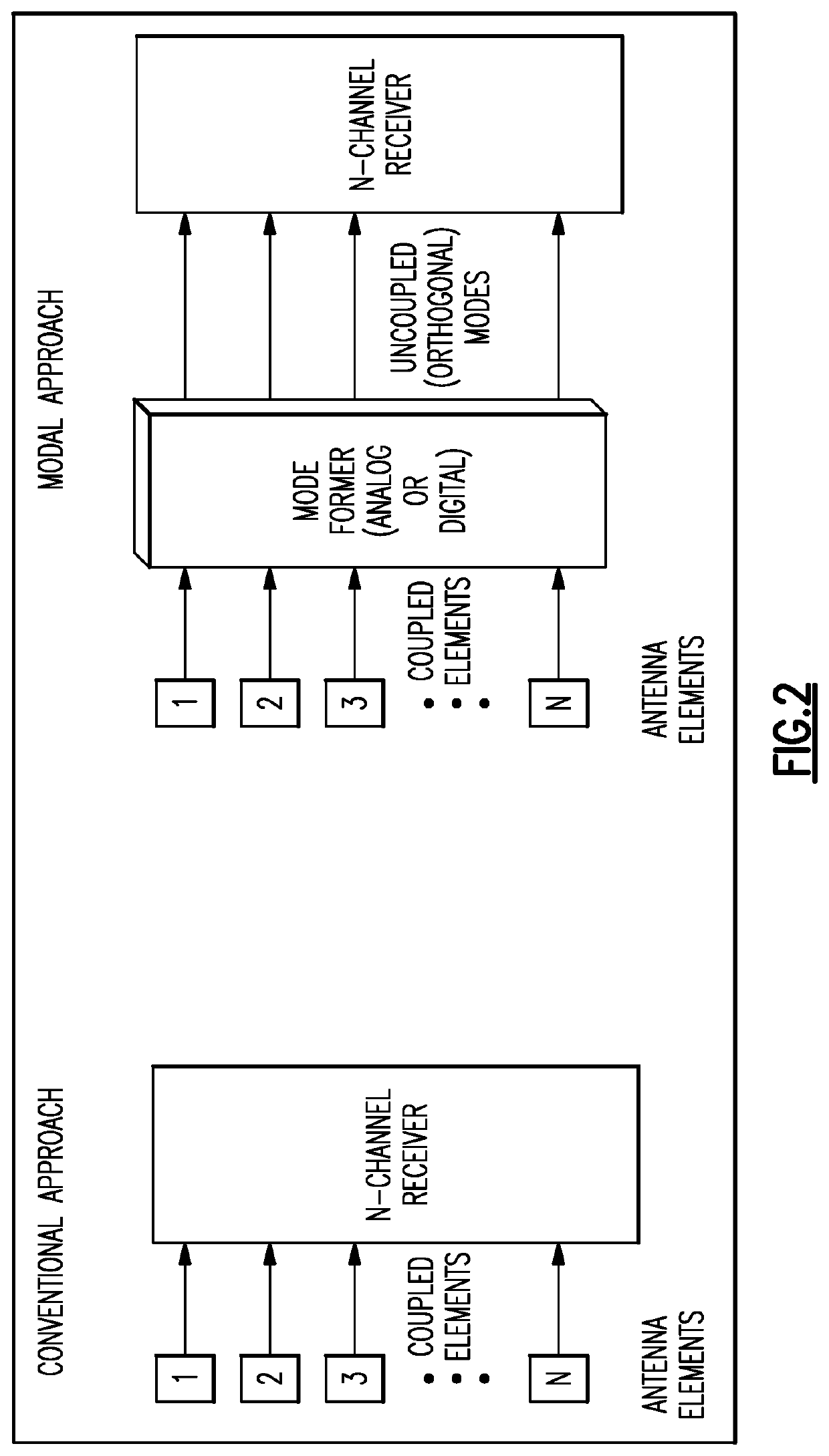
The system and method of global positioning system (GPS) anti-jam (AJ) AJ antennas utilizing a circular array of patch antennas. In some cases the circular array is conformal. The elements are single patch, dual band (L1/L2) and are linearly polarized. A mode former and progressive phase tapers are used.

Description

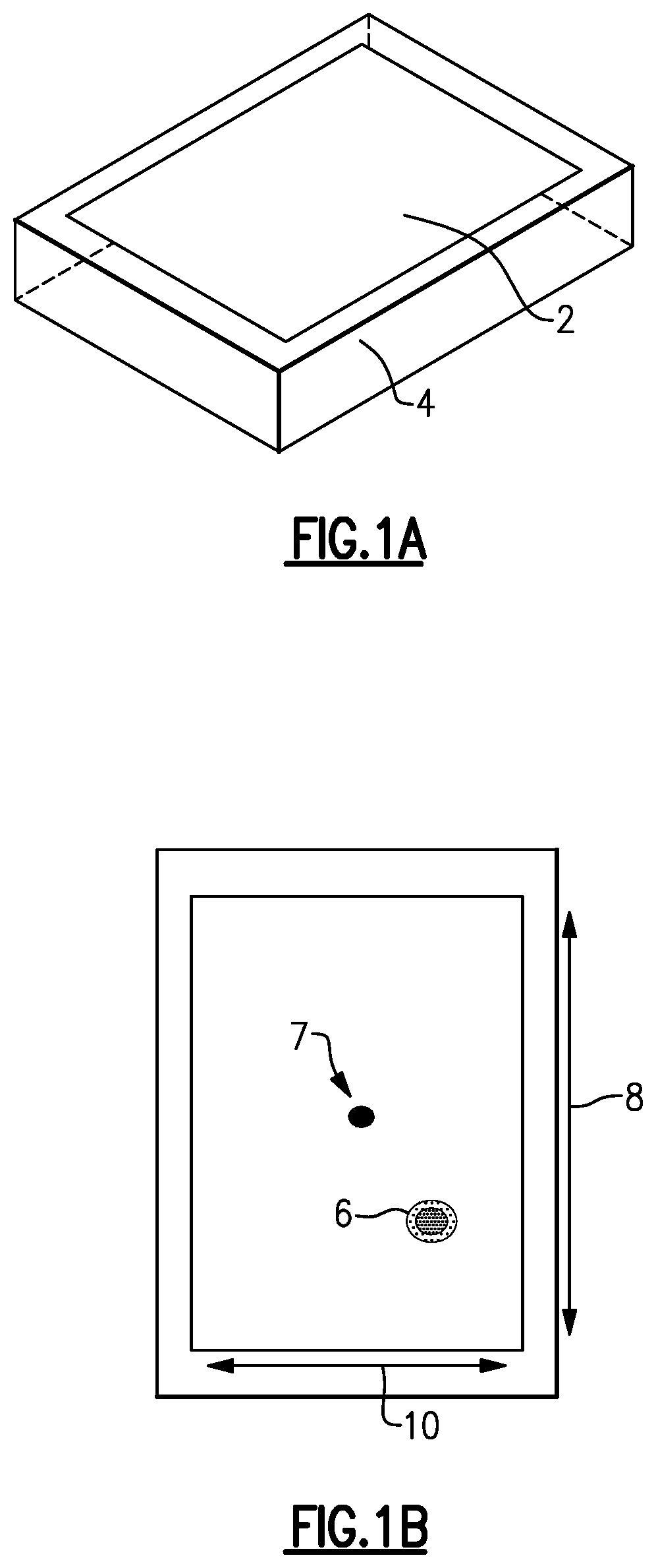
FIELD OF THE DISCLOSURE[0001]The present disclosure relates to anti-jam (AJ) antenna technology and more particularly to global positioning system (GPS) AJ antennas utilizing a circular array of linearly polarized patch antennas.BACKGROUND OF THE DISCLOSURE[0002]Conventional GPS antennas are patch antennas. Patch antennas are typically flat having a ceramic body with a metallization layer on the upper and lower surfaces, and being mounted on a metal base plate. Typically, these patch antennas are square.[0003]A stacked patch antenna for GPS has two ceramic layers bonded together providing two bands, typically L1 and L2. The partially metallized layer on the outer ceramic is tuned to resonate at L1 and is fed from the center conductor passing through both layers to a coax connector attached to the bottom exterior metallized surface of the inner ceramic body. The inner ceramic has an embedded partially metallized layer between the ceramic bodies tuned to resonate at L2. At L1 frequenc...

Claims


Application Information

Patent Timeline
IPC IPC(8): H04K3/00H01Q21/06H01Q21/20H01Q3/26G01S19/21G01S19/36
CPCH04K2203/32H04K3/90H01Q21/205H01Q21/065H01Q3/2611G01S19/36H04K3/224G01S19/21H01Q3/38H01Q21/20
Inventor SCHAY, GARY A.MANCINI, CORRADO
Owner BAE SYST INFORMATION & ELECTRONICS SYST INTERGRATION INC
Why Eureka
Try Eureka